Page 378 of 494

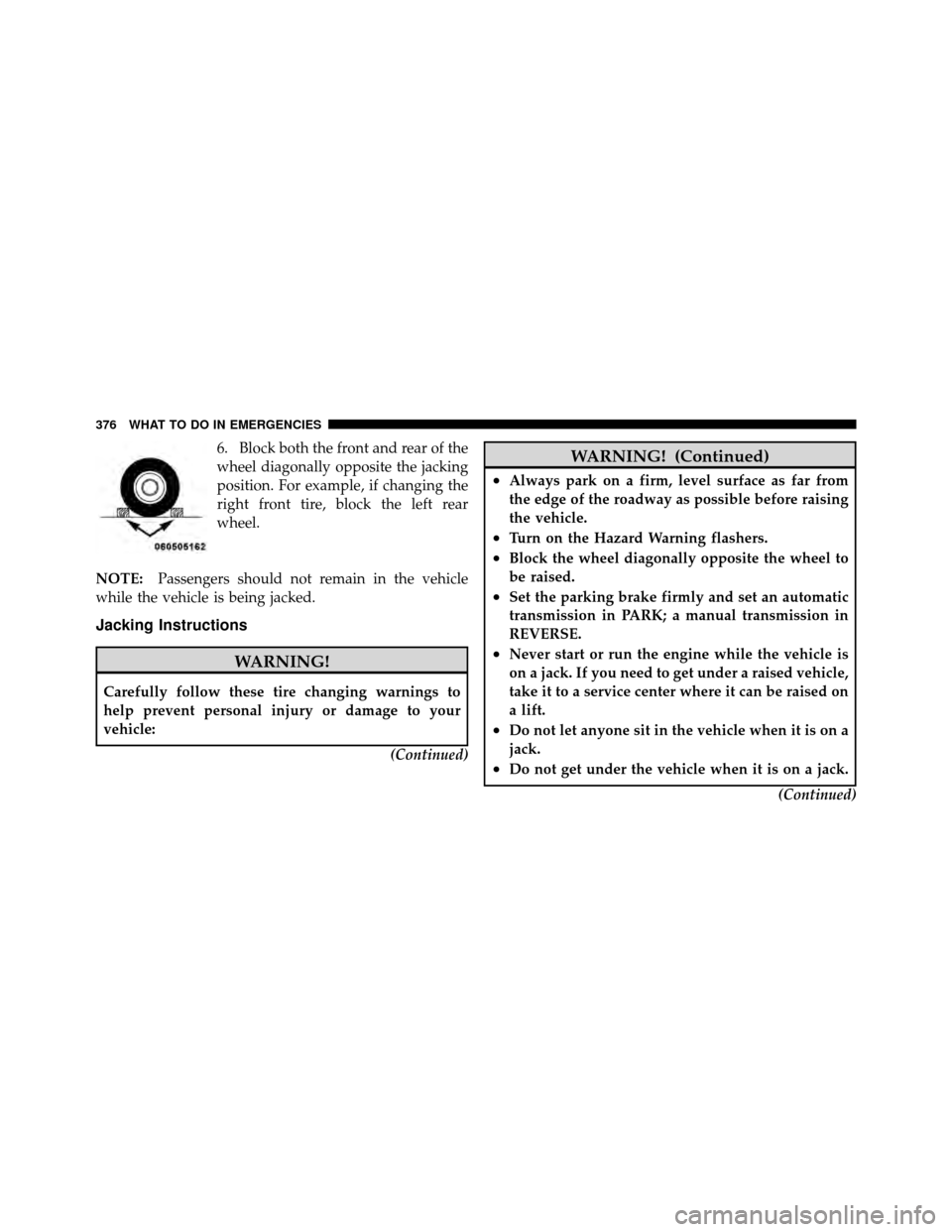
6. Block both the front and rear of the
wheel diagonally opposite the jacking
position. For example, if changing the
right front tire, block the left rear
wheel.
NOTE: Passengers should not remain in the vehicle
while the vehicle is being jacked.
Jacking Instructions
WARNING!
Carefully follow these tire changing warnings to
help prevent personal injury or damage to your
vehicle:
(Continued)
WARNING! (Continued)
•Always park on a firm, level surface as far from
the edge of the roadway as possible before raising
the vehicle.
•Turn on the Hazard Warning flashers.
•Block the wheel diagonally opposite the wheel to
be raised.
•Set the parking brake firmly and set an automatic
transmission in PARK; a manual transmission in
REVERSE.
•Never start or run the engine while the vehicle is
on a jack. If you need to get under a raised vehicle,
take it to a service center where it can be raised on
a lift.
•Do not let anyone sit in the vehicle when it is on a
jack.
•Do not get under the vehicle when it is on a jack.(Continued)
376 WHAT TO DO IN EMERGENCIES
Page 383 of 494

WARNING!
•To avoid the risk of forcing the vehicle off the jack,
do not tighten the wheel nuts fully until the
vehicle has been lowered. Failure to follow this
warning may result in personal injury.
•To avoid possible personal injury, handle the
wheel covers with care to avoid contact with any
sharp edges.
7. Lower the vehicle by turning the jack screw to the left.
8. Finish tightening the nuts. Push down on the wrench
while at the end of the handle for increased leverage.
Tighten the lug nuts in a star pattern until each nut has
been tightened twice. The correct wheel nut torque is
100 ft lbs (135 N·m). If you doubt that you have tightened
the nuts correctly, have them checked with a torque
wrench by your authorized dealer or at a service station. 9. Remove the wheel blocks and lower the jack until it is
free. Reassemble the lug wrench to the jack assembly and
stow it in the spare tire area. Secure the assembly using
the means provided.
WARNING!
A loose tire or jack thrown forward in a collision or
hard stop could endanger the occupants of the ve-
hicle. Always stow the jack parts and the spare tire in
the places provided.
10. Place the deflated (flat) tire in the cargo area and have
the tire repaired or replaced as soon as possible.
11. Check the tire pressure as soon as possible. Correct
the tire pressure as required.
6
WHAT TO DO IN EMERGENCIES 381
Page 385 of 494

3. Align the valve notch in the wheel cover with the
valve stem on the wheel. Install the cover by hand,
snapping the cover over the two lug nuts. Do not use a
hammer or excessive force to install the cover.
4. Install the remaining lug nuts with the cone shaped
end of the nut toward the wheel. Lightly tighten the lug
nuts.
WARNING!
To avoid the risk of forcing the vehicle off the jack,
do not tighten the wheel nuts fully until the vehicle
has been lowered. Failure to follow this warning may
result in personal injury.
5. Lower the vehicle to the ground by turning the jack
handle counterclockwise. 6. Finish tightening the lug nuts. Push down on the
wrench while at the end of the handle for increased
leverage. Tighten the lug nuts in a star pattern until each
nut has been tightened twice. The correct tightness of
each lug nut is 100 ft/lbs (135 N·m). If in doubt about the
correct tightness, have them checked with a torque
wrench by your authorized dealer or service station.
7. After 25 miles (40 km) check the lug nut torque with a
torque wrench to ensure that all lug nuts are properly
seated against the wheel.
Vehicles Without Wheel Covers
1. Mount the road tire on the axle.
2. Install the remaining lug nuts with the cone shaped
end of the nut toward the wheel. Lightly tighten the lug
nuts.
6
WHAT TO DO IN EMERGENCIES 383
Page 386 of 494

WARNING!
To avoid the risk of forcing the vehicle off the jack,
do not tighten the wheel nuts fully until the vehicle
has been lowered. Failure to follow this warning may
result in personal injury.
3. Lower the vehicle to the ground by turning the jack
handle counterclockwise.
4. Finish tightening the lug nuts. Push down on the
wrench while at the end of the handle for increased
leverage. Tighten the lug nuts in a star pattern until each
nut has been tightened twice. The correct tightness of
each lug nut is 100 ft/lbs (135 N·m). If in doubt about the
correct tightness, have them checked with a torque
wrench by your authorized dealer or service station. 5. After 25 miles (40 km) check the lug nut torque with a
torque wrench to ensure that all lug nuts are properly
seated against the wheel.
JUMP-STARTING
If your vehicle has a discharged battery it can be jump-
started using a set of jumper cables and a battery in
another vehicle or by using a portable battery booster
pack. Jump-starting can be dangerous if done improperly
so please follow the procedures in this section carefully.
NOTE:
When using a portable battery booster pack
follow the manufacturer’s operating instructions and
precautions.
384 WHAT TO DO IN EMERGENCIES
Page 397 of 494
MAINTAINING YOUR VEHICLE
CONTENTS
�Engine Compartment — 2.4L ............. 397
� Engine Compartment — 3.6L ............. 398
� Onboard Diagnostic System — OBD II ...... 399
▫ Loose Fuel Filler Cap Message ........... 399
� Emissions Inspection And Maintenance
Programs ............................ 400
� Replacement Parts ..................... 401
� Dealer Service ........................ 402 �
Maintenance Procedures ................. 402
▫ Engine Oil ......................... 403
▫ Engine Oil Filter ..................... 406
▫ Engine Air Cleaner Filter ............... 407
▫ Maintenance-Free Battery .............. 407
▫ Air Conditioner Maintenance ............ 409
▫ A/C Air Filter – If Equipped ............ 410
▫ Body Lubrication .................... 411
▫ Windshield Wiper Blades ............... 412
7
Page 401 of 494

ONBOARD DIAGNOSTIC SYSTEM — OBD II
Your vehicle is equipped with a sophisticated onboard
diagnostic system called OBD II. This system monitors
the performance of the emissions, engine, and automatic
transmission control systems. When these systems are
operating properly, your vehicle will provide excellent
performance and fuel economy, as well as engine emis-
sions well within current government regulations.
If any of these systems require service, the OBD II system
will turn on the “Malfunction Indicator Light” (MIL). It
will also store diagnostic codes and other information to
assist your service technician in making repairs. Al-
though your vehicle will usually be drivable and not
need towing, see your authorized dealer for service as
soon as possible.CAUTION!
•Prolonged driving with the MIL on could cause
further damage to the emission control system. It
could also affect fuel economy and drivability. The
vehicle must be serviced before any emissions
tests can be performed.
•If the MIL is flashing while the engine is running,
severe catalytic converter damage and power loss
will soon occur. Immediate service is required.
Loose Fuel Filler Cap Message
After fuel is added, the vehicle diagnostic system can
determine if the fuel filler cap is possibly loose or
improperly installed. A “GASCAP” message will be
displayed in the instrument cluster. Tighten the gas cap
until a�clicking� sound is heard. This is an indication that
the gas cap is properly tightened. Press the trip odometer
“Reset” button to turn off the message. If the problem
7
MAINTAINING YOUR VEHICLE 399
Page 402 of 494

persists, the message will appear the next time the
vehicle is started. This might indicate a damaged cap. If
the problem is detected twice in a row, the system will
turn on the “Malfunction Indicator Light (MIL).” Resolv-
ing the problem will turn the MIL light off.
EMISSIONS INSPECTION AND MAINTENANCE
PROGRAMS
In some localities, it may be a legal requirement to pass
an inspection of your vehicle’s emissions control system.
Failure to pass could prevent vehicle registration.For states that require an Inspection and Mainte-
nance (I/M), this check verifies the “Malfunction
Indicator Light (MIL)” is functioning and is not
on when the engine is running, and that the OBD II
system is ready for testing. Normally, the OBD II system will be ready. The OBD II
system may
notbe ready if your vehicle was recently
serviced, recently had a dead battery or a battery replace-
ment. If the OBD II system should be determined not
ready for the I/M test, your vehicle may fail the test.
Your vehicle has a simple ignition key-actuated test,
which you can use prior to going to the test station. To
check if your vehicle’s OBD II system is ready, you must
do the following:
1. Turn the ignition switch to the ON position, but do not
crank or start the engine.
2. If you crank or start the engine, you will have to start
this test over.
3. As soon as you turn the ignition switch to the ON
position, you will see the MIL symbol come on as part of
a normal bulb check.
400 MAINTAINING YOUR VEHICLE
Page 403 of 494

4. Approximately 15 seconds later, one of two things will
happen:a. The MIL will flash for about 10 seconds and then
return to being fully illuminated until you turn OFF
the ignition or start the engine. This means that your
vehicle’s OBD II system is not readyand you should
not proceed to the I/M station.
b. The MIL will not flash at all and will remain fully
illuminated until you turn OFF the ignition or start the
engine. This means that your vehicle’s OBD II system
is ready and you can proceed to the I/M station.
If your OBD II system is not ready,you should see your
authorized dealer or repair facility. If your vehicle was
recently serviced or had a battery failure or replacement,
you may need to do nothing more than drive your
vehicle as you normally would in order for your OBD II system to update. A recheck with the above test routine
may then indicate that the system is now ready.
Regardless of whether your vehicle’s OBD II system is
ready or not, if the MIL is illuminated during normal
vehicle operation you should have your vehicle serviced
before going to the I/M station. The I/M station can fail
your vehicle because the MIL is on with the engine
running.
REPLACEMENT PARTS
Use of genuine MOPAR�
parts for normal/scheduled
maintenance and repairs is highly recommended to en-
sure the designed performance. Damage or failures
caused by the use of non-MOPAR� parts for maintenance
and repairs will not be covered by the manufacturer’s
warranty.
7
MAINTAINING YOUR VEHICLE 401