Page 197 of 494

15. Cruise Indicator — If EquippedThis indicator shows that the Electronic Speed
Control System is ON.
16. Odometer/Trip Odometer Reset Button
Dual Trip Odometer
Press and release this button to change the display from
odometer to “Trip A.” Press and release it a second time
to change the display to “Trip B.” Press and release it a
third time to change the display back to the odometer.
To reset the trip odometer, first display the trip mileage
that you want to reset, “Trip A” or “Trip B.” Then push
and hold the button (approximately two seconds) until
the display resets to 0 miles (km). The odometer must be
in Trip Mode to reset the trip odometer. 17. Electronic Throttle Control (ETC) Indicator Light
This light informs you of a problem with the
Electronic Throttle Control (ETC) system. If a
problem is detected, the light will come on
while the engine is running. If the light remains
lit with the engine running, your vehicle will usually be
drivable and not need towing, however see your autho-
rized dealer for service as soon as possible.
If the light is flashing when the engine is running you
may experience power loss, an elevated/rough idle, and
increased brake pedal effort, and your vehicle may
require towing. Immediate service is required.
The light will come on when the ignition switch is first
turned on and remain on approximately 15 seconds as a
bulb check. This is normal. If the light does not come on
during starting, have the system checked by an autho-
rized dealer.
4
UNDERSTANDING YOUR INSTRUMENT PANEL 195
Page 201 of 494

25. Malfunction Indicator Light (MIL)The Malfunction Indicator Light (MIL) is part of
an onboard diagnostic system called OBD that
monitors emissions, engine, and automatic trans-
mission control systems. The light will illuminate when
the key is in the ON/RUN position before engine start. If
the bulb does not come on when turning the key from
LOCK to ON/RUN, have the condition checked
promptly.
Certain conditions, such as a loose or missing gas cap,
poor fuel quality, etc., may illuminate the light after
engine start. The vehicle should be serviced if the light
stays on through several of your typical driving cycles. In
most situations, the vehicle will drive normally and will
not require towing.CAUTION!
Prolonged driving with the MIL on could cause
damage to the engine control system. It also could
affect fuel economy and drivability. If the MIL is
flashing, severe catalytic converter damage and
power loss will soon occur. Immediate service is
required.
WARNING!
A malfunctioning catalytic converter, as referenced
above, can reach higher temperatures than in normal
operating conditions. This can cause a fire if you
drive slowly or park over flammable substances such
as dry plants, wood, cardboard, etc. This could result
in death or serious injury to the driver, occupants or
others.
4
UNDERSTANDING YOUR INSTRUMENT PANEL 199
Page 202 of 494
26. Anti-Lock Brake (ABS) Light — If EquippedThis light monitors the ABS. This light will
come on when the ignition key is turned to the
ON/RUN position and may stay on for ap-
proximately three seconds.
If the ABS light remains on or comes on during driving,
it indicates that the Anti-Lock portion of the brake system
is not functioning and that service is required, however,
the conventional brake system will continue to operate
normally provided that the BRAKE warning light is not
on.
If the ABS light is on, the brake system should be serviced
as soon as possible to restore the benefit of Anti-Lock
Brakes.
The ABS warning light should be checked frequently to
assure that it is operating properly. Turn the ignition key
to the on position, but do not start the vehicle. The light should come on. If the light does not come on, have the
system inspected by an authorized dealer.
27. Transmission Temperature Warning Light — If
Equipped
This light indicates that the transmission fluid
temperature is running hot. This may occur
with severe usage, such as trailer towing. If this
light turns on, safely pull over and stop the
vehicle. Then, shift the transmission into NEUTRAL and
run the engine at idle or faster until the light turns off.
CAUTION!
Continuous driving with the Transmission Tempera-
ture Warning Light illuminated will eventually cause
severe transmission damage or transmission failure.
200 UNDERSTANDING YOUR INSTRUMENT PANEL
Page 203 of 494
WARNING!
If the Transmission Temperature Warning Light is
illuminated and you continue operating the vehicle,
in some circumstances you could cause the fluid to
boil over, come in contact with hot engine or exhaust
components and cause a fire.
28. High Beam Indicator This light indicates that the headlights are on high
beam. Pull the turn signal lever toward the steer-
ing wheel to switch the headlights to low beam.
29. Electronic Vehicle Information Center (EVIC)
Display — If Equipped
This display shows the EVIC messages when the appro-
priate conditions exist. Refer to “Electronic Vehicle Infor-
mation Center (EVIC)” for further information.
MINI-TRIP COMPUTER — IF EQUIPPED
The Mini-Trip Computer is located in the instrument
cluster and features a driver-interactive trip information
and temperature display.
NOTE: The system will display the last known outside
temperature when starting the vehicle and may need to
be driven several minutes before the updated tempera-
ture is displayed. Engine temperature can also affect the
displayed temperature; therefore, temperature readings
are not updated when the vehicle is not moving.
4
UNDERSTANDING YOUR INSTRUMENT PANEL 201
Page 272 of 494
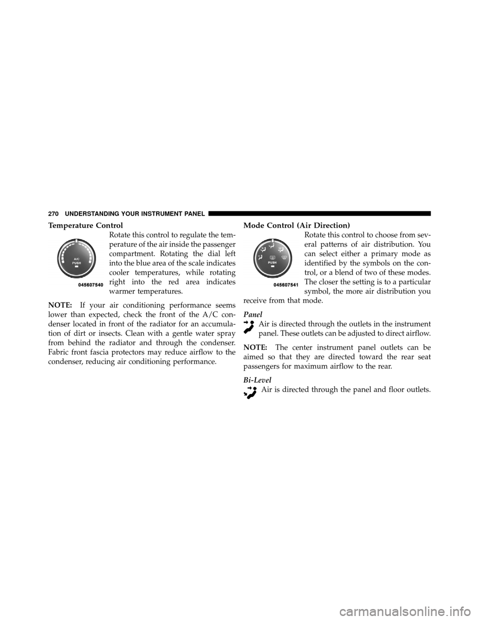
Temperature Control
Rotate this control to regulate the tem-
perature of the air inside the passenger
compartment. Rotating the dial left
into the blue area of the scale indicates
cooler temperatures, while rotating
right into the red area indicates
warmer temperatures.
NOTE: If your air conditioning performance seems
lower than expected, check the front of the A/C con-
denser located in front of the radiator for an accumula-
tion of dirt or insects. Clean with a gentle water spray
from behind the radiator and through the condenser.
Fabric front fascia protectors may reduce airflow to the
condenser, reducing air conditioning performance.
Mode Control (Air Direction)
Rotate this control to choose from sev-
eral patterns of air distribution. You
can select either a primary mode as
identified by the symbols on the con-
trol, or a blend of two of these modes.
The closer the setting is to a particular
symbol, the more air distribution you
receive from that mode.
Panel Air is directed through the outlets in the instrument
panel. These outlets can be adjusted to direct airflow.
NOTE: The center instrument panel outlets can be
aimed so that they are directed toward the rear seat
passengers for maximum airflow to the rear.
Bi-Level Air is directed through the panel and floor outlets.
270 UNDERSTANDING YOUR INSTRUMENT PANEL
Page 279 of 494
The operator can override the AUTO mode setting to
change airflow distribution by rotating the Mode Control
knob (on the right) to one of the following positions.
•PanelAir is directed through the outlets in the instrument
panel. These outlets can be adjusted to direct airflow.
NOTE: The center instrument panel outlets can be
aimed so that they are directed toward the rear seat
passengers for maximum airflow to the rear.
•Bi-Level Air is directed through the panel and floor outlets.
NOTE: For all settings, except full cold or full hot, there
is a difference in temperature between the upper and
lower outlets. The warmer air flows to the floor outlets.
This feature gives improved comfort during sunny but
cool conditions.
•Floor Air is directed through the floor outlets with a
small amount flowing through the defrost and side
window demist outlets.
•Mix Air is directed through the floor, defrost, and side
window demist outlets. This setting works best in
cold or snowy conditions that require extra heat to
the windshield. This setting is good for maintaining
comfort while reducing moisture on the windshield.
•Defrost Air is directed through the windshield and side
window demist outlets. Use this mode with maxi-
mum blower and temperature settings for best wind-
shield and side window defrosting.
4
UNDERSTANDING YOUR INSTRUMENT PANEL 277
Page 282 of 494
Window Fogging
Interior fogging on the windshield can be quickly re-
moved by turning the mode selector to Defrost. The Mix
mode can be used to maintain a clear windshield and
provide sufficient heating. If side window fogging be-
comes a problem, increase blower speed. Vehicle win-
dows tend to fog on the inside in mild but rainy or humid
weather.
NOTE:Recirculate without A/C should not be used for
long periods as fogging may occur.
Side Window Demisters
A side window demister outlet is located at each end of
the instrument panel. These non-adjustable outlets direct
air toward the side windows when the system is in the
FLOOR, MIX, or DEFROST mode. The air is directed at
the area of the windows through which you view the
outside mirrors.
Outside Air Intake
Make sure the air intake, located directly in front of the
windshield, is free of obstructions such as leaves. Leaves
collected in the air intake may reduce airflow, and if they
enter the plenum, they could plug the water drains. In
winter months, make sure the air intake is clear of ice,
slush, and snow.
A/C Air Filter — If Equipped
The A/C Filter prevents most dust and pollen from
entering the cabin. The filter acts on air coming from
outside the vehicle and recirculated air within the pas-
senger compartment. Refer to “Maintenance Procedures”
in “Maintaining Your Vehicle” for A/C Air Filter service
information or see your authorized dealer for service.
Refer to “Maintenance Schedules” for filter service
intervals.
280 UNDERSTANDING YOUR INSTRUMENT PANEL
Page 288 of 494
�Flexible Fuel (3.6L Engine Only) —
If Equipped .......................... 350
▫ E-85 General Information ............... 350
▫ Ethanol Fuel (E-85) ................... 351
▫ Fuel Requirements ................... 352
▫ Selection Of Engine Oil For Flexible Fuel
Vehicles (E-85) And Gasoline Vehicles ...... 352
▫ Starting ........................... 353
▫ Cruising Range ...................... 353
▫ Replacement Parts ................... 353
▫ Maintenance ........................ 354 �
Adding Fuel ......................... 354
▫ Fuel Filler Cap (Gas Cap) .............. 354
▫ Loose Filler Cap Message .............. 356
� Vehicle Loading ...................... 356
▫ Vehicle Certification Label .............. 356
▫ Gross Vehicle Weight Rating (GVWR) ...... 357
▫ Gross Axle Weight Rating (GAWR) ........ 357
▫ Overloading ........................ 358
▫ Loading ........................... 358
� Trailer Towing ........................ 358
▫ Common Towing Definitions ............ 359
▫ Trailer Hitch Classification .............. 361
286 STARTING AND OPERATING