Page 90 of 494
Periodic Safety Checks You Should Make Outside
The Vehicle
Tires
Examine tires for excessive tread wear and uneven wear
patterns. Check for stones, nails, glass, or other objects
lodged in the tread or sidewall. Inspect the tread for cuts
and cracks. Inspect sidewalls for cuts, cracks and bulges.
Check the wheel nuts for tightness. Check the tires
(including spare) for proper cold inflation pressure.
Lights
Have someone observe the operation of exterior lights
while you work the controls. Check turn signal and high
beam indicator lights on the instrument panel.
Door Latches
Check for positive closing, latching, and locking.
Fluid Leaks
Check area under vehicle after overnight parking for fuel,
engine coolant, oil, or other fluid leaks. Also, if gasoline
fumes are detected or if fuel, power steering fluid, or
brake fluid leaks are suspected, the cause should be
located and corrected immediately.
88 THINGS TO KNOW BEFORE STARTING YOUR VEHICLE
Page 101 of 494

WARNING!
Any voice commanded system should be used only
in safe driving conditions following local laws and
phone use. All attention should be kept on the
roadway ahead. Failure to do so may result in a
collision causing serious injury or death.
Uconnect™ Phone Button The radio or steering wheel controls (if
equipped) will contain the two control buttons
(Uconnect™ Phone
button and Voice
Command
button) that will enable you
to access the system. When you press the button you will
hear the word Uconnect™ followed by a BEEP. The beep
is your signal to give a command. Voice Command Button
Actual button location may vary with the ra-
dio. The individual buttons are described in the
“Operation” section.
The Uconnect™ Phone can be used with any Hands-Free
Profile certified Bluetooth� mobile phone. See the
Uconnect™ website for supported phones. Refer to your
mobile service provider or the phone manufacturer for
details.
The Uconnect™ Phone is fully integrated with the vehi-
cle’s audio system. The volume of the Uconnect™ Phone
can be adjusted either from the radio volume control
knob or from the steering wheel radio control (right
switch), if so equipped.
The radio display will be used for visual prompts from
the Uconnect™ Phone such as “CELL” or caller ID on
certain radios.
3
UNDERSTANDING THE FEATURES OF YOUR VEHICLE 99
Page 160 of 494

column) is placed in the AUTO position. In addition, the
headlights will turn off when the wipers are turned off if
they were turned on by this feature.
The headlights with wipers feature can be turned on or
off through the Electronic Vehicle Information Center
(EVIC) — if equipped. Refer to “Electronic Vehicle Infor-
mation Center (EVIC)/Personal Settings (Customer-
Programmable Features)” in “Understanding Your In-
strument Panel” for further information.
TILT/TELESCOPING STEERING COLUMN
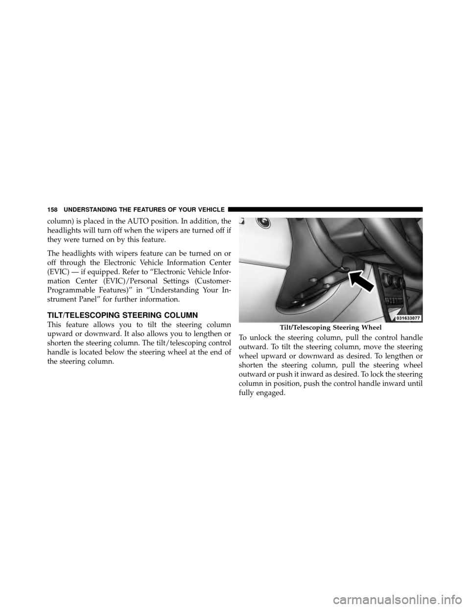
This feature allows you to tilt the steering column
upward or downward. It also allows you to lengthen or
shorten the steering column. The tilt/telescoping control
handle is located below the steering wheel at the end of
the steering column.To unlock the steering column, pull the control handle
outward. To tilt the steering column, move the steering
wheel upward or downward as desired. To lengthen or
shorten the steering column, pull the steering wheel
outward or push it inward as desired. To lock the steering
column in position, push the control handle inward until
fully engaged.Tilt/Telescoping Steering Wheel
158 UNDERSTANDING THE FEATURES OF YOUR VEHICLE
Page 161 of 494
WARNING!
Do not adjust the steering column while driving.
Adjusting the steering column while driving or driv-
ing with the steering column unlocked, could cause
the driver to lose control of the vehicle. Be sure the
steering column is locked before driving your ve-
hicle. Failure to follow this warning may result in
serious injury or death.
ELECTRONIC SPEED CONTROL — IF EQUIPPED
When engaged, the Electronic Speed Control takes over
accelerator operations at speeds greater than 25 mph
(40 km/h).
The Electronic Speed Control buttons are located on the
right side of the steering wheel.NOTE:
In order to ensure proper operation, the Elec-
tronic Speed Control System has been designed to shut
down if multiple Speed Control functions are operated at
the same time. If this occurs, the Electronic Speed Control1 — ON/OFF 2 — RES +
4 — CANCEL 3 — SET -
3
UNDERSTANDING THE FEATURES OF YOUR VEHICLE 159
Page 187 of 494

▫Uconnect™ Multimedia (Satellite Radio) — If
Equipped .......................... 255
� iPod�/USB/MP3 Control — If Equipped ..... 259
▫ Connecting The iPod� Or External USB
Device ............................ 260
▫ Using This Feature ................... 260
▫ Controlling The iPod� Or External USB
Device Using Radio Buttons ............. 261
▫ Play Mode ......................... 261
▫ List Or Browse Mode ................. 263
▫ Bluetooth Streaming Audio (BTSA) ........ 265�
Steering Wheel Audio
Controls — If Equipped .................. 266
▫ Right-Hand Switch Functions ............ 266
▫ Left-Hand Switch Functions For Radio
Operation .......................... 267
▫ Left-Hand Switch Functions For Media
(i.e., CD) Operation ................... 267
� CD/DVD Disc Maintenance .............. 267
� Radio Operation And Mobile Phones ....... 268
� Climate Controls ...................... 268
▫ Manual Heating And Air Conditioning ..... 269
▫ Automatic Temperature Control (ATC) — If
Equipped .......................... 273
▫ Operating Tips ...................... 279
4
UNDERSTANDING YOUR INSTRUMENT PANEL 185
Page 200 of 494

reduces fuel efficiency and tire tread life, and may affect
the vehicle’s handling and stopping ability.
Please note that the TPMS is not a substitute for proper
tire maintenance, and it is the driver ’s responsibility to
maintain correct tire pressure, even if under-inflation has
not reached the level to trigger illumination of the TPMS
low tire pressure telltale.
Your vehicle has also been equipped with a TPMS
malfunction indicator to indicate when the system is not
operating properly. The TPMS malfunction indicator is
combined with the low tire pressure telltale. When the
system detects a malfunction, the telltale will flash for
approximately one minute and then remain continuously
illuminated. This sequence will continue upon subse-
quent vehicle start-ups as long as the malfunction exists.
When the malfunction indicator is illuminated, the sys-
tem may not be able to detect or signal low tire pressure
as intended. TPMS malfunctions may occur for a variety
of reasons, including the installation of replacement oralternate tires or wheels on the vehicle that prevent the
TPMS from functioning properly. Always check the
TPMS malfunction telltale after replacing one or more
tires or wheels on your vehicle, to ensure that the
replacement or alternate tires and wheels allow the TPMS
to continue to function properly.
CAUTION!
The TPMS has been optimized for the original
equipment tires and wheels. TPMS pressures and
warning have been established for the tire size
equipped on your vehicle. Undesirable system opera-
tion or sensor damage may result when using re-
placement equipment that is not of the same size,
type, and/or style. Aftermarket wheels can cause
sensor damage. Do not use tire sealant from a can or
balance beads if your vehicle is equipped with a
TPMS, as damage to the sensors may result.
198 UNDERSTANDING YOUR INSTRUMENT PANEL
Page 203 of 494

WARNING!
If the Transmission Temperature Warning Light is
illuminated and you continue operating the vehicle,
in some circumstances you could cause the fluid to
boil over, come in contact with hot engine or exhaust
components and cause a fire.
28. High Beam Indicator This light indicates that the headlights are on high
beam. Pull the turn signal lever toward the steer-
ing wheel to switch the headlights to low beam.
29. Electronic Vehicle Information Center (EVIC)
Display — If Equipped
This display shows the EVIC messages when the appro-
priate conditions exist. Refer to “Electronic Vehicle Infor-
mation Center (EVIC)” for further information.
MINI-TRIP COMPUTER — IF EQUIPPED
The Mini-Trip Computer is located in the instrument
cluster and features a driver-interactive trip information
and temperature display.
NOTE: The system will display the last known outside
temperature when starting the vehicle and may need to
be driven several minutes before the updated tempera-
ture is displayed. Engine temperature can also affect the
displayed temperature; therefore, temperature readings
are not updated when the vehicle is not moving.
4
UNDERSTANDING YOUR INSTRUMENT PANEL 201
Page 204 of 494
Control Buttons
STEP Button
Press the STEP button located on the steering wheel to
scroll through sub menus (i.e., Temperature, Trip Func-
tions: Odometer, Trip A, Trip B).
RESET Button
To reset the display shown, turn the ignition switch to the
ON position, then press and hold the RESET button
located on the steering wheel.
The following displays can be reset or changed:
•Trip A
•Trip B
Trip Odometer (ODO)
This display shows the distance traveled since the last
reset. Press and release the STEP button on the instru-
ment cluster to switch from odometer, to Trip A or Trip B.
Trip A
Shows the total distance traveled for Trip A since the last
reset.
Trip B
Shows the total distance traveled for Trip B since the last
reset.
Mini-Trip Control Buttons
202 UNDERSTANDING YOUR INSTRUMENT PANEL