Page 133 of 573

turn signal is then activated, and it corresponds to an
alert present on that side of the vehicle, an audible chime
will also be sounded. Whenever a turn signal and de-
tected object are present on the same side at the same
time, both the visual and audio alerts will be issued. In
addition to the audible alert the radio (if on) will also be
muted.
NOTE:
•Whenever an audible alert is requested by the BSM
system, the radio is also muted.
•If the hazard flashers are on, the system will request
the appropriate visual alert only.
When the system is in RCP, the system shall respond
with both visual and audible alerts when a detected
object is present. Whenever an audible alert is re-
quested, the radio is also muted. Turn/hazard signal
status is ignored; the RCP state always requests the
chime.Blind Spot Alert Off
When the BSM system is turned off there will be no
visual or audible alerts from either the BSM or RCP
systems.
NOTE:
The BSM system will store the current operating
mode when the vehicle is shut off. Each time the vehicle
is started the previously stored mode will be recalled and
used.
Uconnect™ Phone — IF EQUIPPED
Uconnect™ Phone is a hands-free system that allows you
to use voice commands to dial a phone number stored in
your mobile phone. Press the Uconnect™ Phone button
on the radio or steering wheel controls (if equipped)
and follow the instructions to pair the mobile phone.
Refer to “Uconnect™ Phone” in the Uconnect™ User
Manual located on the DVD for further details.
130 UNDERSTANDING THE FEATURES OF YOUR VEHICLE
Page 134 of 573
VOICE COMMAND — IF EQUIPPED
Voice Commands can be initiated by pressing the VR
button
located on the radio or steering wheel
controls (if equipped).
Refer to “Voice Command” in the Uconnect™ User
Manual located on the DVD for further details.
SEATS
Seats are a part of the Occupant Restraint System of the
vehicle.
WARNING!
•It is dangerous to ride in a cargo area, inside or
outside of a vehicle. In a collision, people riding in
these areas are more likely to be seriously injured
or killed.
•Do not allow people to ride in any area of your
vehicle that is not equipped with seats and seat
belts. In a collision, people riding in these areas
are more likely to be seriously injured or killed.
•Be sure everyone in your vehicle is in a seat and
using a seat belt properly.
3
UNDERSTANDING THE FEATURES OF YOUR VEHICLE 131
Page 138 of 573

Vehicles Equipped With Remote Start
On models that are equipped with remote start, the
driver ’s heated seat and Heated Steering Wheel can be
programmed to come on during a remote start. Refer to
“Remote Starting System — If Equipped” in “Things To
Know Before Starting Your Vehicle” for further
information.
Front Heated Seats
There are two heated seat switches that allow the driver
and passenger to operate the seats independently. The
controls for each heater are located on the switch bank
below the climate controls.
You can choose from HIGH, LOW or OFF heat settings.
Amber indicator lights in each switch indicate the level of
heat in use. Two indicator lights will illuminate for
HIGH, one for LOW and none for OFF.Press the switch once to select HIGH-level
heating. Press the switch a second time to select
LOW-level heating. Press the switch a third
time to shut the heating elements OFF.
NOTE: Once a heat setting is selected, heat will be felt
within two to five minutes.
When the HIGH-level setting is selected, the heater will
provide a boosted heat level during the initial stages of
operation. Then, the heat output will drop to the normal
HIGH-level. If the HIGH-level setting is selected, the
system will automatically switch to LOW-level after
approximately 30 minutes of continuous operation. At
that time, the number of illuminated LEDs changes from
two to one, indicating the change. The LOW-level setting
will turn OFF automatically after approximately
45 minutes.
3
UNDERSTANDING THE FEATURES OF YOUR VEHICLE 135
Page 170 of 573
Customer-Programmable Features” in “Understanding
Your Instrument Panel” for further information.
TO OPEN AND CLOSE THE HOOD
To open the hood, two latches must be released.
1. Pull the hood release lever located on the instrument
panel, below the steering column.2. Move to the front of the vehicle and look inside the
center of the hood opening. Locate, then push the safety
catch lever downward while raising the hood at the same
time.
Use the hood prop rod to secure the hood in the open
position.
Hood Release
Safety Catch Location
3
UNDERSTANDING THE FEATURES OF YOUR VEHICLE 167
Page 171 of 573
CAUTION!
To prevent possible damage, do not slam the hood to
close it. Lower the hood until it is open approxi-
mately 12 in (30 cm) and then drop it. This should
secure both latches. Never drive your vehicle unless
the hood is fully closed, with both latches engaged.
WARNING!
Be sure the hood is fully latched before driving your
vehicle. If the hood is not fully latched, it could open
when the vehicle is in motion and block your vision.
Failure to follow this warning could result in serious
injury or death.
LIGHTS
All of the lights, except the Hazard Warning lights,
headlight high beams and flash-to-pass, are controlled by
switches to the left of the steering column on the instru-
ment panel.
Headlight Switch With Halo Control Assembly
168 UNDERSTANDING THE FEATURES OF YOUR VEHICLE
Page 176 of 573

Front Fog Lights — If Equipped
To activate the front fog lights, turn on the parking
lights or the low beam headlights and push in the
headlight switch control knob. Pressing the head-
light switch control knob in a second time will turn the
front fog lights off.
Battery Protection
This feature provides battery protection to avoid wearing
down the battery if the headlights, parking lights, or front
fog lights are left on for extended periods of time when
the ignition switch is in the LOCK position. After eight
minutes of the ignition switch being in the LOCK position
and the headlight switch in any position other than OFF
or AUTO, the lights will turn off automatically until the
next cycle of the ignition switch or headlight switch.
The battery protection feature will be disabled if the
ignition switch is turned to any other position other than
LOCK during the eight minute delay.
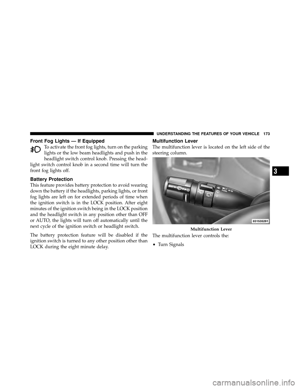
Multifunction Lever
The multifunction lever is located on the left side of the
steering column.
The multifunction lever controls the:
•Turn Signals
Multifunction Lever
3
UNDERSTANDING THE FEATURES OF YOUR VEHICLE 173
Page 179 of 573
Also, dirt, film and other obstructions on the windshield
or camera lens will cause the system to function
improperly.
WINDSHIELD WIPERS AND WASHERS
The wipers and washers are operated by a switch within
the multifunction lever. Rotate the end of the multifunc-
tion lever to select the desired wiper speed.
NOTE:Always remove any buildup of snow that pre-
vents the windshield wiper blades from returning to the
off position. If the windshield wiper switch is turned off
and the blades cannot return to the off position, damage
to the wiper motor may occur.
Mist, Front Wiper And Washer
Use the Mist feature when weather conditions make
occasional usage of the wipers necessary.
Press the end of the multifunction lever inward (toward
the steering column) to the first detent and release for a
single wiping cycle. To use the Washer, push on the end
Washer And Wiper Controls
176 UNDERSTANDING THE FEATURES OF YOUR VEHICLE
Page 183 of 573

TILT/TELESCOPING STEERING COLUMN
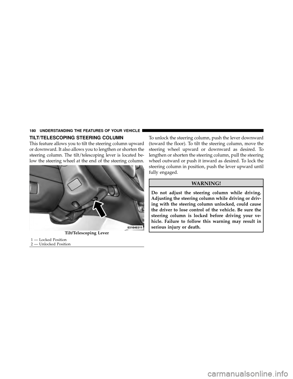
This feature allows you to tilt the steering column upward
or downward. It also allows you to lengthen or shorten the
steering column. The tilt/telescoping lever is located be-
low the steering wheel at the end of the steering column.
To unlock the steering column, push the lever downward
(toward the floor). To tilt the steering column, move the
steering wheel upward or downward as desired. To
lengthen or shorten the steering column, pull the steering
wheel outward or push it inward as desired. To lock the
steering column in position, push the lever upward until
fully engaged.
WARNING!
Do not adjust the steering column while driving.
Adjusting the steering column while driving or driv-
ing with the steering column unlocked, could cause
the driver to lose control of the vehicle. Be sure the
steering column is locked before driving your ve-
hicle. Failure to follow this warning may result in
serious injury or death.
Tilt/Telescoping Lever
1 — Locked Position
2 — Unlocked Position
180 UNDERSTANDING THE FEATURES OF YOUR VEHICLE