Page 322 of 573
•The audio device can be controlled using the radio
buttons to Play, Browse, and List the iPod�contents.
•The audio device battery charges when plugged into
the USB/AUX connector (if supported by the specific
audio device)
Controlling The iPod�Or External USB Device
Using Radio Buttons
To get into the iPod�/USB/MP3 control mode and access
a connected audio device, either press the “AUX” button
on the radio faceplate or press the VR button and say
�USB� or�Switch to USB�. Once in the iPod�/USB/MP3
control mode, audio tracks (if available from audio
device) start playing over the vehicle’s audio system.
Play Mode
When switched to iPod�/USB/MP3 control mode, the
iPod� or external USB device automatically starts Play mode. In Play mode, the following buttons on the radio
faceplate may be used to control the iPod
�or external
USB device and display data:
•Use the TUNE control knob to select the next or
previous track.
•Turning it clockwise (forward) by one click, while
playing a track, skips to the next track or press the
VR button and say �Next Track�.
•Turning it counterclockwise (backward) by one
click, will jump to the previous track in the list or
press the VR button and say �Previous Track�
•Jump backward in the current track by pressing and
holding the <
button long enough will jump to the beginning of
the current track.
•Jump forward in the current track by pressing and
holding the FF>> button.
4
UNDERSTANDING YOUR INSTRUMENT PANEL 319
Page 324 of 573
List Or Browse Mode
During Play mode, pressing any of the buttons described
below, will bring up List mode. List mode enables
scrolling through the list of menus and tracks on the
audio device.
•TUNEcontrol knob: The TUNEcontrol knob functions
in a similar manner as the scroll wheel on the audio
device or external USB device.
•Turning it clockwise (forward) and counterclock-
wise (backward) scrolls through the lists, displaying
the track detail on the radio display. Once the track
to be played is highlighted on the radio display,
press the TUNEcontrol knob to select and start
playing the track. Turning the TUNEcontrol knob
fast will scroll through the list faster. During fast
scroll, a slight delay in updating the information on
the radio display may be noticeable.
•During all List modes, the iPod� displays all lists in
“wrap-around” mode. So if the track is at the
bottom of the list, just turn the wheel backward
(counterclockwise) to get to the track faster.
•In List mode, the radio PRESETbuttons are used as
shortcuts to the following lists on the iPod� or
external USB device.
•Preset 1 – Playlists
•Preset 2 – Artists
•Preset 3 – Albums
•Preset 4 – Genres
•Preset 5 – Audiobooks
•Preset 6 – Podcasts
4
UNDERSTANDING YOUR INSTRUMENT PANEL 321
Page 329 of 573
STEERING WHEEL AUDIO CONTROLS —
IF EQUIPPEDThe remote sound system controls are located on the rear
surface of the steering wheel, at the three and nine
o’clock positions.
The right-hand rocker switch has a pushbutton in the
center, and controls the volume and mode of the sound
system. Pressing the top of the rocker switch will increase
the volume. Pressing the bottom of the rocker switch will
decrease the volume. Pressing the center button changes
the operation of the radio from AM to FM, or to CD
mode, depending on which radio is in the vehicle.
The left-hand rocker switch has a pushbutton in the
center. The function of the left-hand switch is different,
depending on which mode you are in.
The following describes the left-hand rocker switch op-
eration in each mode.
Remote Sound System Controls(Back View Of Steering Wheel)
326 UNDERSTANDING YOUR INSTRUMENT PANEL
Page 342 of 573
CAUTION!
Interior air enters the Rear Manual Climate Control
system through an intake grille, located in the right
side trim panel behind the third row seats. The
heater outlets are located in the right side trim panel,
just behind the sliding door. Do not block or place
objects directly in front of the inlet grille or heater
outlets. The electrical system could overload, causing
damage to the blower motor.
Rear Temperature Control
The rear mode selectionREAR,allows the settings to be
controlled by the rear mode control knob.
To change the temperature in the rear of the vehicle,
rotate the temperature control knob counterclockwise for
cold air, and clockwise for heated air. When rear controls are locked by the front system, the
lock symbol on the temperature knob is illuminated, and
the rear overhead adjustments are inoperable.
Rear Mode Control
Headliner Mode
Air comes from the outlets in the headliner. Each of
these outlets can be individually adjusted to direct
the flow of air. Moving the air vanes of the outlets to one
side will shut off the airflow.
Bi-Level Mode Air comes from both the headliner outlets and the
floor outlets.
NOTE: In many temperature positions, the BI-LEVEL
mode is designed to provide cooler air out of the head-
liner outlets and warmer air from the floor outlets.
4
UNDERSTANDING YOUR INSTRUMENT PANEL 339
Page 347 of 573
To provide you with maximum comfort in the automatic
mode, during cold start-ups, the blower fan will remain
on low until the engine warms up. The fan will engage
immediately if the DEFROST mode is selected, or by
changing the front blower knob setting
Manual Operation
This system offers a full complement of manual override
features. The AUTO symbol in the front ATC display will
be turned off when the system is being used in the
manual mode.
NOTE:Each of these features operate independently
from each other. If any one feature is controlled manually,
the temperature doors will continue to operate automati-
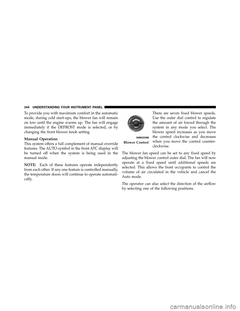
cally. There are seven fixed blower speeds.
Use the outer dial control to regulate
the amount of air forced through the
system in any mode you select. The
blower speed increases as you move
the control clockwise and decreases
when you move the control counter-
clockwise.
The blower fan speed can be set to any fixed speed by
adjusting the blower control outer dial. The fan will now
operate at a fixed speed until additional speeds are
selected. This allows the front occupants to control the
volume of air circulated in the vehicle and cancel the
Auto mode.
The operator can also select the direction of the airflow
by selecting one of the following positions.Blower Control
344 UNDERSTANDING YOUR INSTRUMENT PANEL
Page 351 of 573
2. Rotate the Rear Blower, Rear Temperature and the
Rear Mode Control knobs to suit your comfort needs.
3. ATC is selected by adjusting the rear blower knob
counterclockwise to AUTO.
Once the desired temperature is displayed, the ATC
System will automatically achieve and maintain that
comfort level. When the system is set up for your comfort
level, it is not necessary to change the settings. You will
experience the greatest efficiency by simply allowing the
system to function automatically.
NOTE:
•It is not necessary to move the temperature settings for
cold or hot vehicles. The system automatically adjusts
the temperature, mode and fan speed to provide
comfort as quickly as possible.
•The temperature can be displayed in English or Metric
units by selecting the “Display Units of Measure in”customer-programmable feature. Refer to the “Elec-
tronic Vehicle Information Center (EVIC) — Customer-
Programmable Features” in this Section.
Rear Blower Control
The rear blower control knob can be manually set to off,
or any fixed blower speed, by rotating the knob from low
to high. This allows the rear seat occupants to control the
volume of air circulated in the rear of the vehicle.
CAUTION!
Interior air enters the Rear Automatic Temperature
Control System through an intake grille, located in
the right side trim panel behind the third row seats.
The heater outlets are located in the right side trim
panel, just behind the sliding door. Do not block or
place objects directly in front of the inlet grille or
heater outlets. The electrical system could overload
causing damage to the blower motor.
348 UNDERSTANDING YOUR INSTRUMENT PANEL
Page 352 of 573

Rear Temperature Control
To change the temperature in the rear of the vehicle,
rotate the temperature knob counterclockwise to lower
the temperature, and clockwise to increase the tempera-
ture. The rear temperature settings are displayed in the
front ATC panel.
When rear controls are locked by the front system, the
Rear Temperature Lock symbol on the temperature knob
is illuminated and any rear overhead adjustments are
ignored.
Rear Mode Control
Auto Mode
The rear system automatically maintains the correct
mode and comfort level desired by the rear seat occu-
pants.Headliner Mode
Air comes from the outlets in the headliner. Each of
these outlets can be individually adjusted to direct
the flow of air. Moving the air vanes of the outlets to one
side will shut off the airflow.
Bi-Level Mode Air comes from both the headliner outlets and the
floor outlets.
NOTE: In many temperature positions, the BI-LEVEL
mode is designed to provide cooler air out of the head-
liner outlets and warmer air from the floor outlets.
Floor Mode Air comes from the floor outlets.
Summer Operation
The engine cooling system in air conditioned vehicles
must be protected with a high-quality antifreeze coolant
4
UNDERSTANDING YOUR INSTRUMENT PANEL 349
Page 361 of 573
Do notpress the accelerator. Use the Fob with Integrated
Key to briefly turn the ignition switch to the START
position and release it as soon as the starter engages. The
starter motor will continue to run, and it will disengage
automatically when the engine is running. If the engine
fails to start, the starter will disengage automatically in
10 seconds. If this occurs, turn the ignition switch to the
LOCK position, wait 10 to 15 seconds, then repeat the
“Normal Starting” procedure.
Keyless Enter-N-Go – If Equipped
This feature allows the driver to oper-
ate the ignition switch with the push
of a button, as long as the ENGINE
START/STOP button is installed and
the Remote Keyless Entry (RKE) trans-
mitter is in the passenger compart-
ment.
Installing And Removing The ENGINE
START/STOP Button
Installing The Button
1. Remove the key fob from the ignition switch.
2. Insert the ENGINE START/STOP button into the
ignition switch with the lettering facing up and readable.
3. Press firmly on the center of the button to secure it into
position.
Removing The Button
1. The ENGINE START/STOP button can be removed
from the ignition switch for key fob use.
2. Insert the metal part of the emergency key under the
chrome bezel at the 6 o’clock position and gently pry the
button loose.
358 STARTING AND OPERATING