Page 441 of 573

WARNING! (Continued)
•Make certain that the load is secured in the trailer
and will not shift during travel. When trailering
cargo that is not fully secured, dynamic load shifts
can occur that may be difficult for the driver to
control. You could lose control of your vehicle and
have a collision.
•When hauling cargo or towing a trailer, do not
overload your vehicle or trailer. Overloading can
cause a loss of control, poor performance or dam-
age to brakes, axle, engine, transmission, steering,
suspension, chassis structure or tires.
•Safety chains must always be used between your
vehicle and trailer. Always connect the chains to
the frame or hook retainers of the vehicle hitch.
Cross the chains under the trailer tongue and
allow enough slack for turning corners.(Continued)
WARNING! (Continued)
•Vehicles with trailers should not be parked on a
grade. When parking, apply the parking brake on
the tow vehicle. Put the tow vehicle automatic
transmission in PARK. Always, block or �chock�
the trailer wheels.
•GCWR must not be exceeded.
•Total weight must be distributed between the tow
vehicle and the trailer such that the following four
ratings are not exceeded:
1. GVWR
2. GTW
3. GAWR
4. Trailer tongue weight rating for that trailer
hitch. (This requirement may limit the ability to
always achieve the 10% to 15% range of trailer
tongue weight as a percentage of total trailer
weight.)
438 STARTING AND OPERATING
Page 442 of 573
Towing Requirements – Tires
•
Do not attempt to tow a trailer while using a compact
spare tire.
•Proper tire inflation pressures are essential to the safe
and satisfactory operation of your vehicle. Refer to
“Tires – General Information” in “Starting and Oper-
ating” for proper tire inflation procedures.
•Check the trailer tires for proper tire inflation pres-
sures before trailer usage.
•Check for signs of tire wear or visible tire damage
before towing a trailer. Refer to “Tires – General
Information” in “Starting and Operating” for the
proper inspection procedure.
•When replacing tires, refer to “Tires – General Infor-
mation” in “Starting and Operating” for proper tirereplacement procedures. Replacing tires with a higher
load carrying capacity will not increase the vehicle’s
GVWR and GAWR limits.
Towing Requirements – Trailer Brakes
•
Do
not interconnect the hydraulic brake system or
vacuum system of your vehicle with that of the trailer.
This could cause inadequate braking and possible
personal injury.
•An electronically actuated trailer brake controller is
required when towing a trailer with electronically
actuated brakes. When towing a trailer equipped with
a hydraulic surge actuated brake system, an electronic
brake controller is not required.
•Trailer brakes are recommended for trailers over
1,000 lbs (454 kg) and required for trailers in excess of
2,000 lbs (907 kg).
5
STARTING AND OPERATING 439
Page 443 of 573
CAUTION!
If the trailer weighs more than 1,000 lbs (454 kg)
loaded, it should have its own brakes and they
should be of adequate capacity. Failure to do this
could lead to accelerated brake lining wear, higher
brake pedal effort, and longer stopping distances.
WARNING!
•Do not connect trailer brakes to your vehicle’s
hydraulic brake lines. It can overload your brake
system and cause it to fail. You might not have
brakes when you need them and could have a
collision.(Continued)
WARNING! (Continued)
•Towing any trailer will increase your stopping
distance. When towing you should allow for addi-
tional space between your vehicle and the vehicle
in front of you. Failure to do so could result in an
collision.
Towing Requirements – Trailer Lights And Wiring
Whenever you pull a trailer, regardless of the trailer size,
stop lights and turn signals on the trailer are required for
motoring safety.
The Trailer Tow Package may include a four-pin or a
seven-pin wiring harness. Use a factory approved trailer
harness and connector.
NOTE:Do not cut or splice wiring into the vehicles
wiring harness.
440 STARTING AND OPERATING
Page 444 of 573
The electrical connections are all complete to the vehicle
but you must mate the harness to a trailer connector.
Refer to the following four-pin connector and seven-pin
connector illustrations.
Four-Pin Connector
1 — Female Pins4 — Park
2 — Male Pin 5 — Left Stop/Turn
3 — Ground 6 — Right Stop/Turn
Seven-Pin Connector
1 — Battery5 — Ground
2 — Backup Lamps 6 — Left Stop/Turn
3 — Right Stop/Turn 7 — Running Lamps
4 — Electric Brakes
5
STARTING AND OPERATING 441
Page 476 of 573
MAINTAINING YOUR VEHICLE
CONTENTS
�Engine Compartment — 3.6L ............. 475
� Onboard Diagnostic System — OBD II ...... 476
▫ Loose Fuel Filler Cap Message ........... 476
� Emissions Inspection And Maintenance
Programs ............................ 477
� Replacement Parts ..................... 478
� Dealer Service ........................ 479
� Maintenance Procedures ................. 479
▫ Engine Oil ......................... 480 ▫
Engine Oil Filter ..................... 482
▫ Engine Air Cleaner Filter ............... 483
▫ Exhaust System ..................... 483
▫ Maintenance-Free Battery .............. 485
▫ Air Conditioner Maintenance ............ 487
▫ Body Lubrication .................... 489
▫ Windshield Wiper Blades ............... 490
▫ Cooling System ..................... 491
▫ Brakes ............................ 497
7
Page 500 of 573
•Do not change the thermostat for Summer or Winter
operation. If replacement is ever necessary, install
ONLY the correct type thermostat. Other designs may
result in unsatisfactory coolant performance, poor gas
mileage, and increased emissions.
Brakes
In order to assure brake system performance, all brake
system components should be inspected periodically.
Refer to the “Maintenance Schedule” for the proper
maintenance intervals.
WARNING!
Riding the brakes can lead to brake failure and
possibly a collision. Driving with your foot resting or
riding on the brake pedal can result in abnormally
high brake temperatures, excessive lining wear, and
possible brake damage. You would not have your full
braking capacity in an emergency.
Master Cylinder – Brake Fluid Level Check
The fluid level in the master cylinder should be checked
when performing underhood services, or immediately if
the “Brake System Warning Light” indicates system
failure.
Clean the top of the master cylinder area before removing
the cap. Add fluid to bring the level up to the top of the
“FULL” mark on the side of the master cylinder reservoir.
Overfilling of fluid is not recommended because it may
cause leaking in the system.
Add enough fluid to bring the level up to the require-
ments described on the brake fluid reservoir. With disc
brakes, fluid level can be expected to fall as the brake
pads wear. However, low fluid level may be caused by a
leak and a checkup may be needed.
7
MAINTAINING YOUR VEHICLE 497
Page 511 of 573
CAUTION!
•When installing the Totally Integrated Power
Module cover, it is important to ensure the cover is
properly positioned and fully latched. Failure to
do so may allow water to get into the Integrated
Power Module, and possibly result in a electrical
system failure.
•When replacing a blown fuse, it is important to
use only a fuse having the correct amperage rating.
The use of a fuse with a rating other than indicated
may result in a dangerous electrical system over-
load. If a properly rated fuse continues to blow, it
indicates a problem in the circuit that must be
corrected.
The numbers inside the TIPM cover correspond to the
following table.
Cavity Cartridge
Fuse Mini-
Fuse Description
J1 40 Amp Green — Power Folding Seat
J2 30 Amp Pink — Power Liftgate Mod-
ule
J3 30 Amp Pink — Rear Door Module
(RR Door Node)
J4 25 Amp Natural — Driver Door Node
J5 25 Amp Natural — Passenger Door Node
J6 40 Amp Green — Antilock Brakes
Pump/Stability Con-
trol System
J7 30 Amp Pink — Antilock Brakes
Valve/Stability Con-
trol System
508 MAINTAINING YOUR VEHICLE
Page 516 of 573
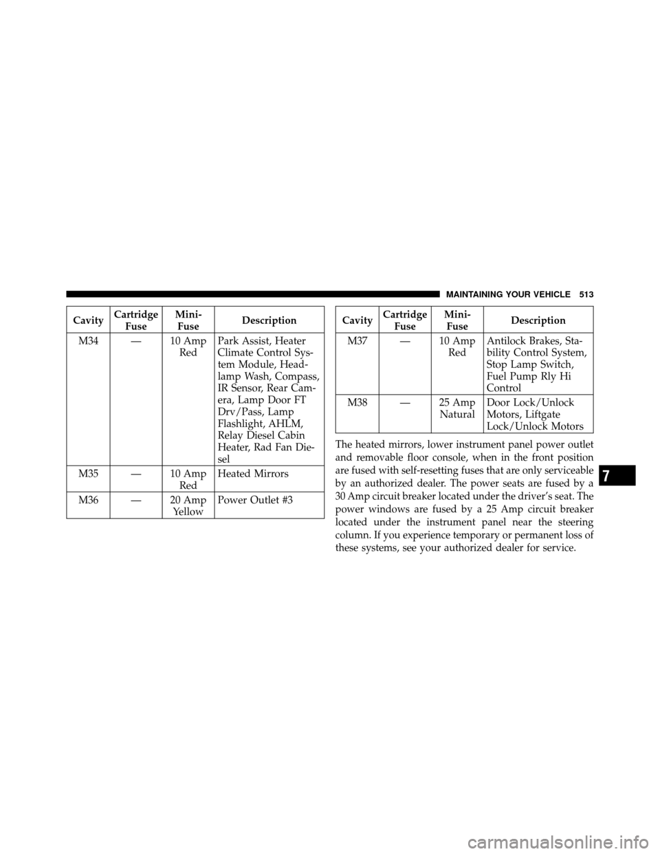
CavityCartridge
Fuse Mini-
Fuse Description
M34 — 10 Amp RedPark Assist, Heater
Climate Control Sys-
tem Module, Head-
lamp Wash, Compass,
IR Sensor, Rear Cam-
era, Lamp Door FT
Drv/Pass, Lamp
Flashlight, AHLM,
Relay Diesel Cabin
Heater, Rad Fan Die-
sel
M35 — 10 Amp RedHeated Mirrors
M36 — 20 Amp YellowPower Outlet #3Cavity
Cartridge
Fuse Mini-
Fuse Description
M37 — 10 Amp RedAntilock Brakes, Sta-
bility Control System,
Stop Lamp Switch,
Fuel Pump Rly Hi
Control
M38 — 25 Amp NaturalDoor Lock/Unlock
Motors, Liftgate
Lock/Unlock Motors
The heated mirrors, lower instrument panel power outlet
and removable floor console, when in the front position
are fused with self-resetting fuses that are only serviceable
by an authorized dealer. The power seats are fused by a
30 Amp circuit breaker located under the driver’s seat. The
power windows are fused by a 25 Amp circuit breaker
located under the instrument panel near the steering
column. If you experience temporary or permanent loss of
these systems, see your authorized dealer for service.
7
MAINTAINING YOUR VEHICLE 513