2011 CHRYSLER 200 CONVERTIBLE wheel
[x] Cancel search: wheelPage 313 of 505

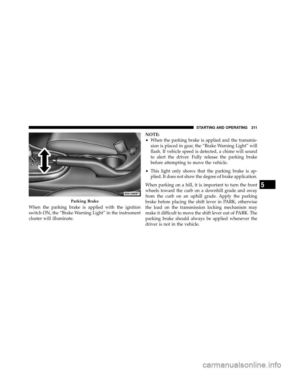
When the parking brake is applied with the ignition
switch ON, the “Brake Warning Light” in the instrument
cluster will illuminate.NOTE:
•When the parking brake is applied and the transmis-
sion is placed in gear, the “Brake Warning Light” will
flash. If vehicle speed is detected, a chime will sound
to alert the driver. Fully release the parking brake
before attempting to move the vehicle.
•This light only shows that the parking brake is ap-
plied. It does not show the degree of brake application.
When parking on a hill, it is important to turn the front
wheels toward the curb on a downhill grade and away
from the curb on an uphill grade. Apply the parking
brake before placing the shift lever in PARK, otherwise
the load on the transmission locking mechanism may
make it difficult to move the shift lever out of PARK. The
parking brake should always be applied whenever the
driver is not in the vehicle.
Parking Brake
5
STARTING AND OPERATING 311
Page 315 of 505

ANTI-LOCK BRAKE SYSTEM (ABS)
The Anti-Lock Brake System (ABS) provides increased
vehicle stability and brake performance under most
braking conditions. The system operates with a separate
computer to modulate the hydraulic pressure to prevent
wheel lock-up and avoid skidding on slippery surfaces.
WARNING!
•Pumping of the anti-lock brakes will diminish
their effectiveness and may lead to a collision.
Pumping makes the stopping distance longer. Just
press firmly on your brake pedal when you need
to slow down or stop.
•The ABS cannot prevent the natural laws of phys-
ics from acting on the vehicle, nor can it increase
braking or steering efficiency beyond that af-
forded by the condition of the vehicle brakes and
tires or the traction afforded.(Continued)
WARNING! (Continued)
•The ABS cannot prevent collisions, including
those resulting from excessive speed in turns,
following another vehicle too closely, or hydro-
planing.
•The capabilities of an ABS-equipped vehicle must
never be exploited in a reckless or dangerous
manner, which could jeopardize the user’s safety
or the safety of others.
The “Anti-Lock Brake Warning Light” moni-
tors the Anti-Lock Brake System. The light will
come on when the ignition switch is turned to
the ON position and may stay on for as long as
four seconds.
If the “Anti-Lock Brake Warning Light” remains on or
comes on while driving, it indicates that the anti-lock
portion of the brake system is not functioning and that
5
STARTING AND OPERATING 313
Page 317 of 505

WARNING!
The Anti-Lock Brake System contains sophisticated
electronic equipment that may be susceptible to
interference caused by improperly installed or high
output radio transmitting equipment. This interfer-
ence can cause possible loss of anti-lock braking
capability. Installation of such equipment should be
performed by qualified professionals.
All vehicle wheels and tires must be the same size and
type, and tires must be properly inflated to produce
accurate signals for the computer.
ELECTRONIC BRAKE CONTROL SYSTEM
Your vehicle may be equipped with an optional ad-
vanced electronic brake control system that includes
Anti-Lock Brake System (ABS), Traction Control System
(TCS), Brake Assist System (BAS), Hill Start Assist (HSA),
and Electronic Stability Control (ESC). All systems work together to enhance vehicle stability and control in vari-
ous driving conditions and are commonly referred to as
ESC.
Anti-Lock Brake System (ABS)
This system aids the driver in maintaining vehicle control
under adverse braking conditions. The system controls
hydraulic brake pressure to prevent wheel lock-up and
help avoid skidding on slippery surfaces during braking.
Refer to “Anti-Lock Brake System” in “Starting and
Operating” for further information.
Traction Control System (TCS)
This system monitors the amount of wheel spin of each of
the driven wheels. If wheel spin is detected, brake
pressure is applied to the slipping wheel(s) and engine
power is reduced to provide enhanced acceleration and
stability. A feature of the TCS system functions similar to
a limited slip differential and controls the wheel spin
across a driven axle. If one wheel on a driven axle is
5
STARTING AND OPERATING 315
Page 318 of 505

spinning faster than the other, the system will apply the
brake of the spinning wheel. This will allow more engine
torque to be applied to the wheel that is not spinning.
This feature remains active even if TCS and ESC are in
the “Partial Off” mode. Refer to “Electronic Stability
Control (ESC)” in this section of this manual.
Brake Assist System (BAS)
The BAS is designed to optimize the vehicle’s braking
capability during emergency braking maneuvers. The
system detects an emergency braking situation by sens-
ing the rate and amount of brake application and then
applies optimum pressure to the brakes. This can help
reduce braking distances. The BAS complements the
Anti-Lock Brake System (ABS). Applying the brakes very
quickly results in the best BAS assistance. To receive the
benefit of the system, you must apply continuous brak-
ing pressure during the stopping sequence. Do notreduce brake pedal pressure unless braking is no longer
desired. Once the brake pedal is released, the BAS is
deactivated.
WARNING!
•The BAS cannot prevent the natural laws of phys-
ics from acting on the vehicle, nor can it increase
braking efficiency beyond that afforded by the
condition of the vehicle brakes and tires or the
traction afforded.
•The BAS cannot prevent collisions, including
those resulting from excessive speed in turns,
following another vehicle too closely, or hydro-
planing.
•The capabilities of a BAS-equipped vehicle must
never be exploited in a reckless or dangerous
manner, which could jeopardize the user ’s safety
or the safety of others.
316 STARTING AND OPERATING
Page 320 of 505

The system will only work if the intended direction of the
vehicle and vehicle gear match. For example, if the
intended direction is forward up a hill and the vehicle is
in DRIVE and the activation criteria are met, HSA will
activate.
The system will work in REVERSE and all forward gears,
and will not activate if the vehicle is placed in NEUTRAL.
HSA Off
Non-EVIC Equipped Vehicles
If you wish to turn off the HSA system, follow this
procedure:
NOTE:You must complete Steps 1 through 8 within
90 seconds.
1. Center the steering wheel (front wheels pointing
straight forward).
2. Shift the transmission into NEUTRAL. 3. Apply the parking brake.
4. Start the engine.
5. Release the clutch pedal.
6. Rotate the steering wheel one-half turn to the left.
7. Press the “ESC Off” switch four times within 20 sec-
onds. The “ESC Activation/Malfunction Indicator Light”
should turn on and turn off two times.
8. Rotate the steering wheel back to center and then an
additional half-turn to the right.
9. Turn the ignition switch to the OFF position and then
back to the ON position. If the sequence was completed
properly, the “ESC Activation/Malfunction Indicator
Light” will blink several times to confirm HSA is dis-
abled.
10. Repeat these steps if you want to return this feature
to it’s previous setting.
318 STARTING AND OPERATING
Page 321 of 505

EVIC Equipped Vehicles
HSA is a Customer Programmable Feature on a EVIC
equipped vehicle. If you wish to turn off the HSA feature,
refer to “Electronic Vehicle Information Center (EVIC)/
Customer Programmable Features” in “Understanding
Your Instrument Panel” for further information.
Electronic Stability Control (ESC)
This system enhances directional control and stability of
the vehicle under various driving conditions. ESC cor-
rects for over/under steering of the vehicle by applying
the brake of the appropriate wheel to assist in counter-
acting the over/under steer condition. Engine power
may also be reduced to help the vehicle maintain the
desired path. ESC uses sensors in the vehicle to deter-
mine the vehicle path intended by the driver and com-
pares it to the actual path of the vehicle. When the actual
path does not match the intended path, ESC applies the
brake of the appropriate wheel to assist in counteracting
the oversteer or understeer condition
•Over-steer - when the vehicle is turning more than
appropriate for the steering wheel position.
•Under-steer - when the vehicle is turning less than
appropriate for the steering wheel position.
WARNING!
Electronic Stability Control (ESC) cannot prevent the
natural laws of physics from acting on the vehicle, nor
can it increase the traction afforded by prevailing
road conditions. ESC cannot prevent accidents, in-
cluding those resulting from excessive speed in turns,
driving on very slippery surfaces, or hydroplaning.
ESC also cannot prevent accidents resulting from loss
of vehicle control due to inappropriate driver input
for the conditions. Only a safe, attentive, and skillful
driver can prevent accidents. The capabilities of an
ESC equipped vehicle must never be exploited in a
reckless or dangerous manner which could jeopardize
the user ’s safety or the safety of others.
5
STARTING AND OPERATING 319
Page 322 of 505

ESC Operating Modes
All ESC equipped vehicles can choose the following ESC
operating modes:
ESC On
This is the normal operating mode for ESC. Whenever
the vehicle is started the ESC system will be in this mode.
This mode should be used for almost all driving situa-
tions. ESC should only be turned to “Partial Off” for
specific reasons as noted below.
Partial ESC Mode
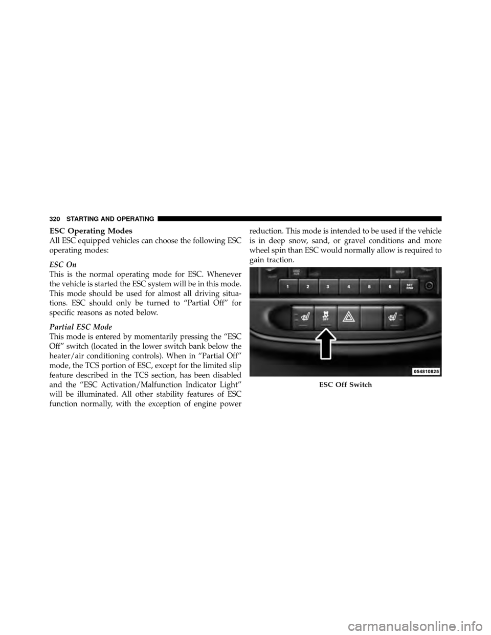
This mode is entered by momentarily pressing the “ESC
Off” switch (located in the lower switch bank below the
heater/air conditioning controls). When in “Partial Off”
mode, the TCS portion of ESC, except for the limited slip
feature described in the TCS section, has been disabled
and the “ESC Activation/Malfunction Indicator Light”
will be illuminated. All other stability features of ESC
function normally, with the exception of engine powerreduction. This mode is intended to be used if the vehicle
is in deep snow, sand, or gravel conditions and more
wheel spin than ESC would normally allow is required to
gain traction.
ESC Off Switch
320 STARTING AND OPERATING
Page 338 of 505

Spare Tire Matching Original Equipped Tire and
Wheel – If Equipped
The spare tire of your vehicle is equivalent in look and
function as the original equipment tire and wheel found
on the front or rear axle of your vehicle. This spare tire
may be used in the tire rotation for your vehicle. If your
vehicle has an option for a spare tire matching original
equipment tire and wheel, refer to the recommended tire
rotation pattern in “Tire Rotation Recommendations” in
“Starting and Operating” for further information.
If your vehicle is not equipped with an original equip-
ment tire and wheel as a spare, a non-matching tempo-
rary emergency use spare may be equipped with your
vehicle. Temporary use spares are engineered to be used
only with your vehicle. Your vehicle may be equipped
with one of the following types of non-matching tempo-
rary use spares; compact, full size, or limited-use.Do not install more than one non-matching temporary
use spare tire/wheel on the vehicle at any given time.
CAUTION!
Because of the reduced ground clearance, do not take
your vehicle through an automatic car wash with a
compact, full size or limited-use temporary spare
installed. Damage to the vehicle may result.
Compact Spare Tire – If Equipped
The compact spare is for temporary emergency use only.
You can identify if your vehicle is equipped with a
compact spare by looking at the spare tire description on
the Tire and Loading Information Placard located on the
driver ’s side door opening or on the sidewall of the tire.
Compact spare tire descriptions begin with the letter “T”
or “S” preceding the size designation. Example: T145/
80D18 103M.
336 STARTING AND OPERATING