2011 CHEVROLET MALIBU instrument cluster
[x] Cancel search: instrument clusterPage 227 of 382
Black plate (33,1)Chevrolet Malibu Owner Manual - 2011
Driving and Operating 9-33
If the system fails to turn on or
activate, the ESC/TCS light will be
on solid, and the ESC OFF or
SERVICE ESC message will be
displayed.
For more information, seeRide
Control System Messages
on
page 5‑28.
This light will flash on the instrument
panel cluster when the ESC system
is both on and activated.
The system may be heard or felt
while it is working; this is normal.
When the light is on solid and either
the SERVICE ESC or ESC OFF
message is displayed, the system
will not assist the driver in
maintaining directional control of the vehicle. Adjust your driving
accordingly. See
Ride Control
System Messages on page 5‑28.
The Electronic Stability Control
(ESC) system is automatically
enabled whenever the vehicle is
started. To assist the driver with
vehicle directional control,
especially in slippery road
conditions, the system should
always be left on. But, ESC can be
turned off if needed.
If the vehicle is in cruise control
when the system begins to assist
the driver maintain directional
control of the vehicle, the ESC/TCS
light will flash and the cruise control
will automatically disengage. The
cruise control system may be
re-engaged when road conditions
allow. See Cruise Control
on
page 9‑34.
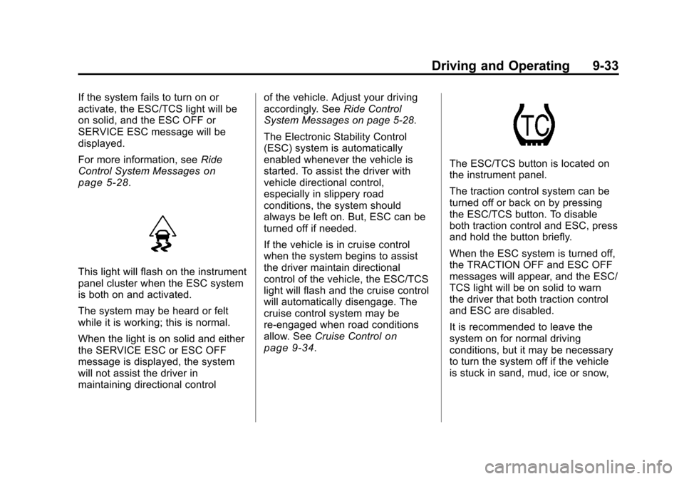
The ESC/TCS button is located on
the instrument panel.
The traction control system can be
turned off or back on by pressing
the ESC/TCS button. To disable
both traction control and ESC, press
and hold the button briefly.
When the ESC system is turned off,
the TRACTION OFF and ESC OFF
messages will appear, and the ESC/
TCS light will be on solid to warn
the driver that both traction control
and ESC are disabled.
It is recommended to leave the
system on for normal driving
conditions, but it may be necessary
to turn the system off if the vehicle
is stuck in sand, mud, ice or snow,
Page 229 of 382
Black plate (35,1)Chevrolet Malibu Owner Manual - 2011
Driving and Operating 9-35
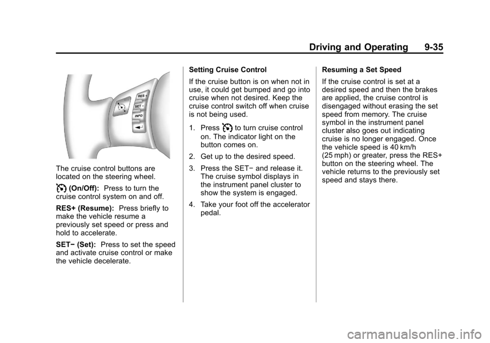
The cruise control buttons are
located on the steering wheel.
I(On/Off):Press to turn the
cruise control system on and off.
RES+ (Resume): Press briefly to
make the vehicle resume a
previously set speed or press and
hold to accelerate.
SET− (Set): Press to set the speed
and activate cruise control or make
the vehicle decelerate. Setting Cruise Control
If the cruise button is on when not in
use, it could get bumped and go into
cruise when not desired. Keep the
cruise control switch off when cruise
is not being used.
1. Press
Ito turn cruise control
on. The indicator light on the
button comes on.
2. Get up to the desired speed.
3. Press the SET− and release it.
The cruise symbol displays in
the instrument panel cluster to
show the system is engaged.
4. Take your foot off the accelerator pedal. Resuming a Set Speed
If the cruise control is set at a
desired speed and then the brakes
are applied, the cruise control is
disengaged without erasing the set
speed from memory. The cruise
symbol in the instrument panel
cluster also goes out indicating
cruise is no longer engaged. Once
the vehicle speed is 40 km/h
(25 mph) or greater, press the RES+
button on the steering wheel. The
vehicle returns to the previously set
speed and stays there.
Page 261 of 382
Black plate (19,1)Chevrolet Malibu Owner Manual - 2011
Vehicle Care 10-19
By this time, the coolant level
inside the coolant surge tank
might be lower. If the level is
lower than the FULL COLD
mark, add more of the proper
mixture to the coolant surge tank
until the level reaches the FULL
COLD mark.
5. Then replace the pressure cap. Be sure the pressure cap is
hand-tight and fully seated.
Notice: If the pressure cap is not
tightly installed, coolant loss and
possible engine damage may
occur. Be sure the cap is properly
and tightly secured.
Engine Overheating
The vehicle has several indicators
to warn of engine overheating.
There is an engine coolant
temperature gauge as well as an
engine coolant temperature warning
light on the vehicle's instrument
panel cluster. See Engine Coolant Temperature Gauge on page 5‑20
and
Engine Coolant Temperature
Warning Light on page 5‑20.
If it is decided not to lift the hood
when this warning appears, but
instead get service help right away.
See Roadside Assistance Program
(United States and Canada)
on
page 13‑7or Roadside Assistance
Program (Mexico) on page 13‑9.
If it is decided to lift the hood, make
sure the vehicle is parked on a level
surface.
Then check to see if the engine
cooling fans are running. If the
engine is overheating, both fans
should be running. If they are not,
do not continue to run the engine
and have the vehicle serviced.
Notice: Engine damage from
running the engine without
coolant is not covered by the
warranty.
If Steam is Coming from the
Engine Compartment
{WARNING
Steam from an overheated engine
can burn you badly, even if you
just open the hood. Stay away
from the engine if you see or hear
steam coming from it. Just turn it
off and get everyone away from
the vehicle until it cools down.
Wait until there is no sign of
steam or coolant before you open
the hood.
If you keep driving when your
engine is overheated, the liquids
in it can catch fire. You or others
could be badly burned. Stop your
engine if it overheats, and get out
of the vehicle until the engine
is cool.
Page 276 of 382
Black plate (34,1)Chevrolet Malibu Owner Manual - 2011
10-34 Vehicle Care
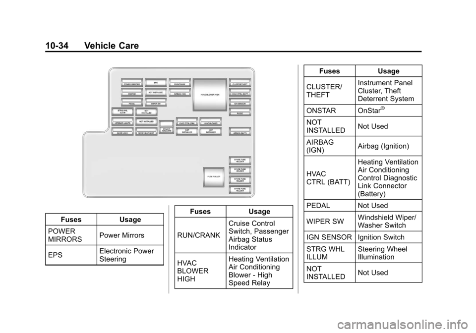
FusesUsage
POWER
MIRRORS Power Mirrors
EPS Electronic Power
Steering Fuses
Usage
RUN/CRANK Cruise Control
Switch, Passenger
Airbag Status
Indicator
HVAC
BLOWER
HIGH Heating Ventilation
Air Conditioning
Blower - High
Speed Relay Fuses
Usage
CLUSTER/
THEFT Instrument Panel
Cluster, Theft
Deterrent System
ONSTAR OnStar
®
NOT
INSTALLED Not Used
AIRBAG
(IGN) Airbag (Ignition)
HVAC
CTRL (BATT) Heating Ventilation
Air Conditioning
Control Diagnostic
Link Connector
(Battery)
PEDAL Not Used
WIPER SW Windshield Wiper/
Washer Switch
IGN SENSOR Ignition Switch
STRG WHL
ILLUM Steering Wheel
Illumination
NOT
INSTALLED Not Used
Page 290 of 382
Black plate (48,1)Chevrolet Malibu Owner Manual - 2011
10-48 Vehicle Care
The TPMS malfunction indicator is
combined with the low tire pressure
telltale. When the system detects a
malfunction, the telltale will flash for
approximately one minute and then
remain continuously illuminated.
This sequence will continue upon
subsequent vehicle start‐ups as
long as the malfunction exists.
When the malfunction indicator is
illuminated, the system may not be
able to detect or signal low tire
pressure as intended. TPMS
malfunctions may occur for a variety
of reasons, including the installation
of replacement or alternate tires or
wheels on the vehicle that prevent
the TPMS from functioning properly.
Always check the TPMS malfunction
telltale after replacing one or more
tires or wheels on your vehicle to
ensure that the replacement or
alternate tires and wheels allow the
TPMS to continue to function
properly.
SeeTire Pressure Monitor
Operation
on page 10‑48for
additional information.
Federal Communications
Commission (FCC) and
Industry Canada
See Radio Frequency Statementon
page 13‑17for information regarding
Part 15 of the Federal
Communications Commission (FCC)
rules and Industry Canada
Standards RSS-210/220/310.
Tire Pressure Monitor
Operation
This vehicle may have a Tire
Pressure Monitor System (TPMS).
The TPMS is designed to warn the
driver when a low tire pressure
condition exists. TPMS sensors are
mounted onto each tire and wheel
assembly, excluding the spare tire
and wheel assembly. The TPMS
sensors monitor the air pressure in
the vehicle's tires and transmits the
tire pressure readings to a receiver
located in the vehicle.
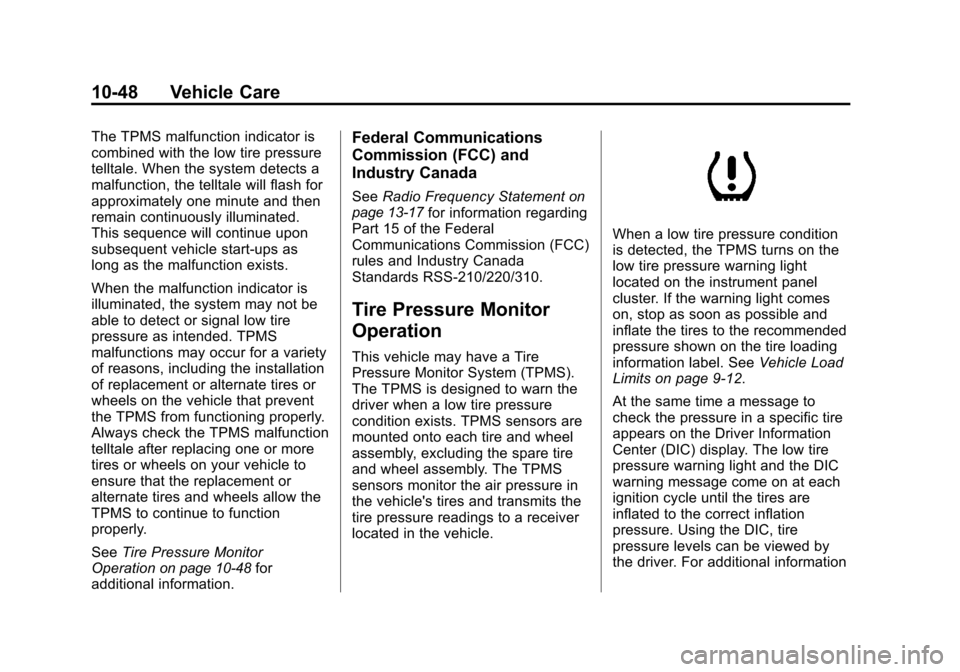
When a low tire pressure condition
is detected, the TPMS turns on the
low tire pressure warning light
located on the instrument panel
cluster. If the warning light comes
on, stop as soon as possible and
inflate the tires to the recommended
pressure shown on the tire loading
information label. See Vehicle Load
Limits on page 9‑12.
At the same time a message to
check the pressure in a specific tire
appears on the Driver Information
Center (DIC) display. The low tire
pressure warning light and the DIC
warning message come on at each
ignition cycle until the tires are
inflated to the correct inflation
pressure. Using the DIC, tire
pressure levels can be viewed by
the driver. For additional information
Page 376 of 382

Black plate (6,1)Chevrolet Malibu Owner Manual - 2011
i-6 INDEX
I
Ignition Positions . . . . . . . . . . . . . . 9-18
Ignition Transmission LockCheck . . . . . . . . . . . . . . . . . . . . . . . 10-26
Immobilizer . . . . . . . . . . . . . . . . . . . . 2-13
Infants and Young Children, Restraints . . . . . . . . . . . . . . . . . . . . 3-40
Instrument Cluster . . . . . . . . . . . . . 5-10
Instrument Panel Storage Area . . . . . . . . . . . . . . . . . . 4-1
Introduction . . . . . . . . . . . . . . . . . . .iii, 7-1
J
Jump Starting . . . . . . . . . . . . . . . . . 10-78
K
Key and Lock Messages . . . . . . . 5-28
Keyless Entry
Remote (RKE) System . . . . . . . . 2-3
Keyless Entry System . . . . . . . . . . 2-2
Keys . . . . . . . . . . . . . . . . . . . . . . . . . . . . 2-2
L
Labeling, Tire Sidewall . . . . . . . . 10-40
Lamp Messages . . . . . . . . . . . . . . . 5-28
Lamps
Daytime Running (DRL) . . . . . . . 6-3
Dome . . . . . . . . . . . . . . . . . . . . . . . . . . 6-5
Exterior Controls . . . . . . . . . . . . . . . 6-1
Exterior Lamps OffReminder . . . . . . . . . . . . . . . . . . . . 6-2
License Plate . . . . . . . . . . . . . . . 10-29
Malfunction Indicator . . . . . . . . . 5-16
Reading . . . . . . . . . . . . . . . . . . . . . . . 6-5
Lap-Shoulder Belt . . . . . . . . . . . . . 3-17
LATCH System Replacing Parts After aCrash . . . . . . . . . . . . . . . . . . . . . . . 3-54
Latch, Lower Anchors and Tethers for Children . . . . . . . . . . 3-47
Lighting Entry/Exit . . . . . . . . . . . . . . . . . . . . . . 6-6
Illumination Control . . . . . . . . . . . . 6-5
Parade Dimming . . . . . . . . . . . . . . . 6-6 Lights
Airbag Readiness . . . . . . . . . . . . . 5-14
Antilock Brake System
(ABS) Warning . . . . . . . . . . . . . . 5-19
Charging System . . . . . . . . . . . . . 5-15
Cruise Control . . . . . . . . . . . . . . . . 5-23
Engine Coolant Temperature Warning . . . . . . . 5-20
Engine Oil Pressure . . . . . . . . . . 5-22
Flash-to-Pass . . . . . . . . . . . . . . . . . . 6-3
High-Beam On . . . . . . . . . . . . . . . . 5-23
High/Low Beam Changer . . . . . . 6-2
Safety Belt Reminders . . . . . . . . 5-13
Security . . . . . . . . . . . . . . . . . . . . . . 5-22
Tire Pressure . . . . . . . . . . . . . . . . . 5-21
Locks
Automatic Door . . . . . . . . . . . . . . . . 2-9
Delayed Locking . . . . . . . . . . . . . . . 2-8
Door . . . . . . . . . . . . . . . . . . . . . . . . . . . 2-7
Lockout Protection . . . . . . . . . . . . . 2-9
Power Door . . . . . . . . . . . . . . . . . . . . 2-8
Safety . . . . . . . . . . . . . . . . . . . . . . . . . 2-9
Loss of Control . . . . . . . . . . . . . . . . . 9-6
Low-Profile Tires . . . . . . . . . . . . . . 10-39