2011 BMW X5 XDRIVE 35I SPORT ACTIVITY ignition
[x] Cancel search: ignitionPage 82 of 312
Controls Overview
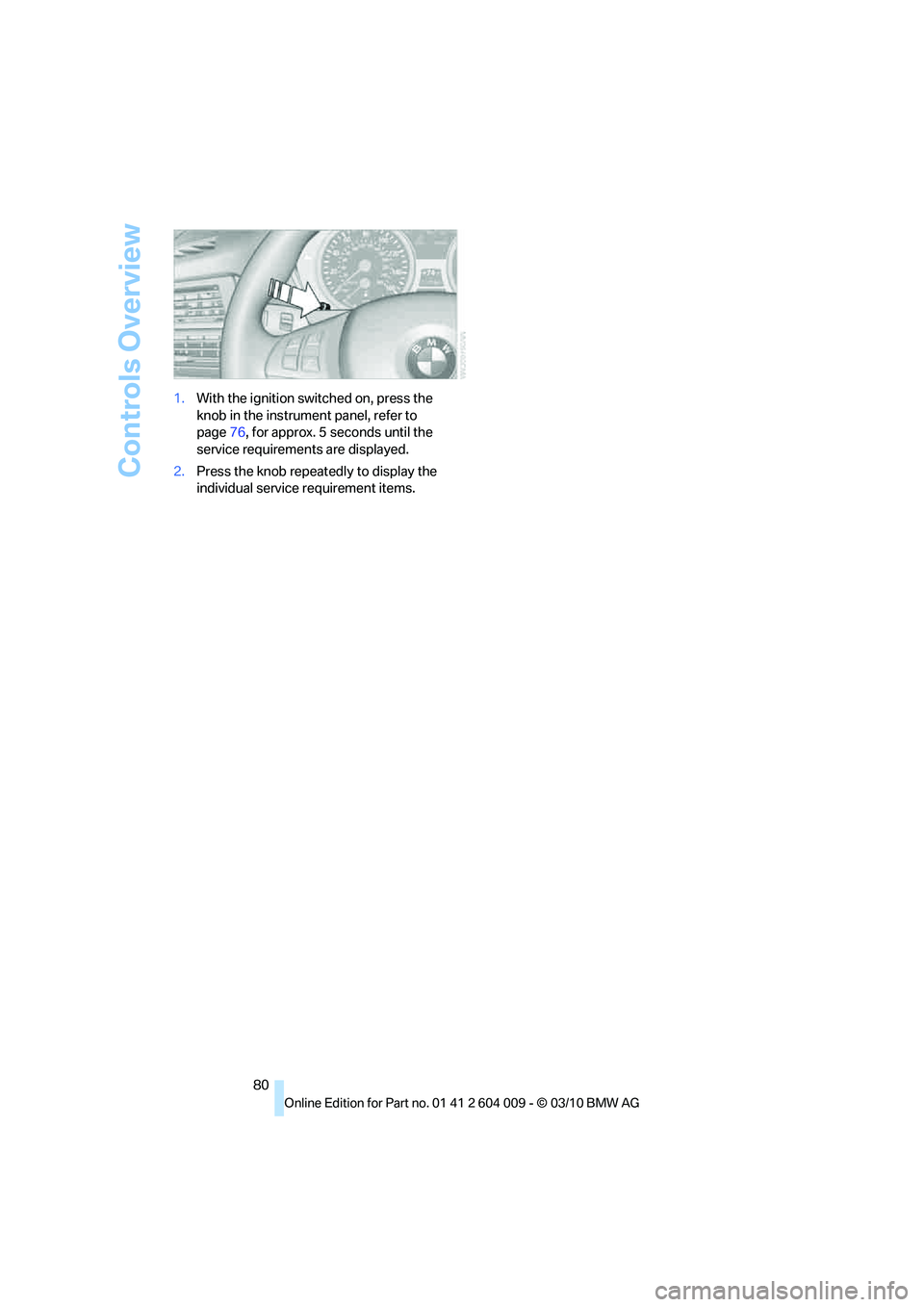
80 1.With the ignition switched on, press the
knob in the instrument panel, refer to
page76, for approx. 5 seconds until the
service requirements are displayed.
2.Press the knob repeatedly to display the
individual service requirement items.
Page 90 of 312

Technology for comfort, convenience and safety
88
Technology for comfort, convenience and
safety
PDC Park Distance Control*
The concept
In addition to the PDC Park Distance Control,
the rear view camera
*, refer to page93, can
also be switched on.
PDC assists you during parking. A slow
approach to an object in front of or behind your
vehicle is announced by:
>Signal tones
>Optical displays
Measurement
Ultrasonic sensors in the bumpers carry out the
measurement.
Their range is approx. 7 ft/2 m.
The acoustic warning begins:
>At approx. 24 in/60 cm for the front
* sen-
sors and the two rear corner sensors.
>At approx. 5 ft/1.50 m for the middle sen-
sors in the rear.
System limitations
PDC cannot replace the personal assess-
ment of the traffic situation. Also make a
direct visual check of the traffic situation around
the vehicle. Otherwise, there could be a risk of
accident, for example due to other road users or
objects outside the detection range of PDC.
Loud sources of sound, inside and outside the
vehicle, could drown out the PDC signal tone.<
Avoid approaching an object too quickly.
Avoid starting off quickly while PDC is not
yet activated.
Otherwise, physical circumstances could cause
the system to issue a warning late.<
Limitations of ultrasonic measurement
The detection of objects can come up against
the limitations of physical ultrasonic measure-
ment, for example:
>When using tow bars and towing hitches
>In the presence of thin or wedge-shaped
objects
>In the presence of low objects
>In the presence of objects with corners and
sharp edges
Low objects that have already been displayed,
e.g. curbs, can disappear again from the detec-
tion area of the sensors before or after a contin-
uous tone sounds.
Higher, protruding objects, e.g. ledges, cannot
be detected.
False warnings
Under the following conditions, PDC may dis-
play a warning even though no obstacle is
present in the detection range:
>In heavy rain
>When the sensors are heavily soiled or iced-
over
>When the sensors are covered with snow
>On rough road surfaces
>In large, rectangular buildings with smooth
walls, e.g. underground garages
>In the presence of heavy exhaust
>Due to the presence of other ultrasonic
sources such as street sweepers, steam
cleaners, or neon lamps.
Automatic activation
With the engine running or the ignition switched
on, shift the selector lever into position R.
Automatic deactivation
The system switches off and the LED goes out:
Page 92 of 312

Technology for comfort, convenience and safety
90
Malfunction
A Check Control message appears in the
instrument panel, refer to page82.
The areas in front of and behind the vehicle
appear in shaded form on the Control Display.
PDC is malfunctioning. Have the system
checked.
In order to assure full functionality:
>Keep sensors clean and free of ice.
>Do not spray the sensors with high-pres-
sure cleaners for long periods and keep the
spray nozzle at least 12 in/30 cm away from
them.
Surround View*
The concept
Surround View encompasses the following sys-
tems:
>Top View
*, refer to page90
>Side View
*, refer to page92
>Rear view camera
*, refer to page93
It provides assistance when parking and
maneuvering and at blind driveways and inter-
sections.
Top View*
The concept
Top View assists you when parking and maneu-
vering. To accomplish this, the door region and
road surface region are shown on the Control
Display.
Detection
Detection is carried out by two cameras inte-
grated into the exterior mirror and the rear view
camera.
The range is:
>Approx. 7 ft/2 m to the side
>Approx. 7 ft/2 m to the rear
Obstacles up to the height of the exterior mir-
rors are thus detected in a timely fashion.
System limitations
In the following situations, the function of Top
View is limited:
>When a door is open
>When the liftgate is open
>When the exterior mirrors are folded in
>Under poor lighting conditions
The arrows next to the vehicle are displayed in a
shaded form on the Control Display and a sym-
bol appears at the corresponding location on
the vehicle.
Also make a direct visual check of the
traffic situation around the vehicle. Other-
wise, there could be a risk of accident, for exam-
ple due to other road users or objects outside
the image range of the camera.<
Automatic activation
With the engine running or the ignition switched
on, shift the selector lever into position R.
The images from Top View and PDC are dis-
played when the system has been switched on
using iDrive.
Automatic deactivation
The system switches off and the LED goes out:
>After approx. 165 ft/50 m when driving for-
ward
>At speeds over approx. 25 mph/35 km/h
when driving forward
Switch the system back on as needed.
Page 95 of 312
Controls
93Reference
At a glance
Driving tips
Communications
Navigation
Entertainment
Mobility
Cameras
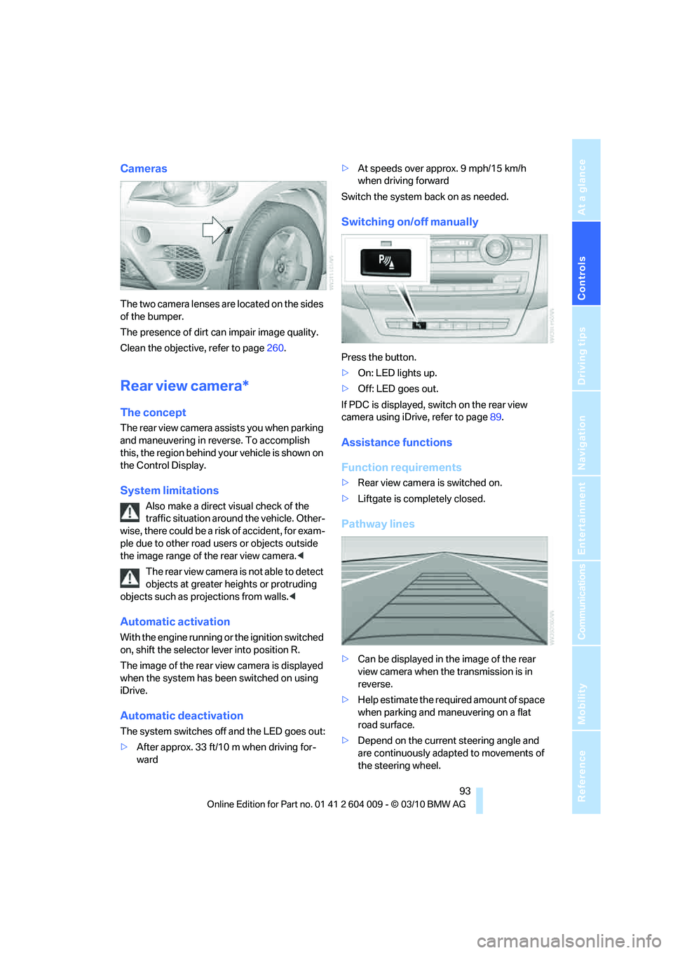
The two camera lenses are located on the sides
of the bumper.
The presence of dirt can impair image quality.
Clean the objective, refer to page260.
Rear view camera*
The concept
The rear view camera assists you when parking
and maneuvering in reverse. To accomplish
this, the region behind your vehicle is shown on
the Control Display.
System limitations
Also make a direct visual check of the
traffic situation around the vehicle. Other-
wise, there could be a risk of accident, for exam-
ple due to other road users or objects outside
the image range of the rear view camera.<
T he r e a r v i e w c a m e r a i s n o t a b l e t o de t e c t
objects at greater heights or protruding
objects such as projections from walls.<
Automatic activation
With the engine running or the ignition switched
on, shift the selector lever into position R.
The image of the rear view camera is displayed
when the system has been switched on using
iDrive.
Automatic deactivation
The system switches off and the LED goes out:
>After approx. 33 ft/10 m when driving for-
ward>At speeds over approx. 9 mph/15 km/h
when driving forward
Switch the system back on as needed.
Switching on/off manually
Press the button.
>On: LED lights up.
>Off: LED goes out.
If PDC is displayed, switch on the rear view
camera using iDrive, refer to page89.
Assistance functions
Function requirements
>Rear view camera is switched on.
>Liftgate is completely closed.
Pathway lines
>Can be displayed in the image of the rear
view camera when the transmission is in
reverse.
>Help estimate the required amount of space
when parking and maneuvering on a flat
road surface.
>Depend on the current steering angle and
are continuously adapted to movements of
the steering wheel.
Page 113 of 312
Controls
111Reference
At a glance
Driving tips
Communications
Navigation
Entertainment
Mobility
Lamps
Parking lamps/low beams
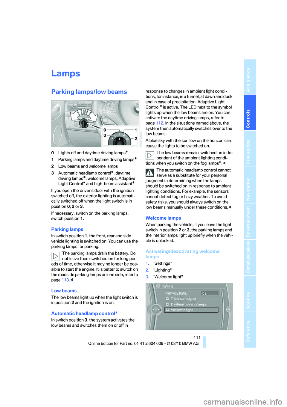
0Lights off and daytime driving lamps*
1Parking lamps and daytime driving lamps*
2Low beams and welcome lamps
3Automatic headlamp control
*, daytime
driving lamps
*, welcome lamps, Adaptive
Light Control
* and high-beam assistant*
If you open the driver's door with the ignition
switched off, the exterior lighting is automati-
cally switched off when the light switch is in
position0, 2 or 3.
If necessary, switch on the parking lamps,
switch position1.
Parking lamps
In switch position1, the front, rear and side
vehicle lighting is switched on. You can use the
parking lamps for parking.
The parking lamps drain the battery. Do
not leave them switched on for long peri-
ods of time, otherwise it may no longer be pos-
sible to start the engine. It is better to switch on
the roadside parking lamps on one side, refer to
page113.<
Low beams
The low beams light up when the light switch is
in position 2 and the ignition is on.
Automatic headlamp control*
In switch position3, the system activates the
low beams and switches them on or off in response to changes in ambient light condi-
tions, for instance, in a tunnel, at dawn and dusk
and in case of precipitation. Adaptive Light
Control
* is active. The LED next to the symbol
lights up when the low beams are on. You can
activate the daytime driving lamps, refer to
page112. In the situations named above, the
system then automatically switches over to the
low beams.
A blue sky with the sun low on the horizon can
cause the lights to be switched on.
The low beams remain switched on inde-
pendent of the ambient lighting condi-
tions when you switch on the fog lamps
*.<
The automatic headlamp control cannot
serve as a substitute for your personal
judgment in determining when the lamps
should be switched on in response to ambient
lighting conditions. For example, the sensors
cannot detect fog or hazy weather. To avoid
safety risks, you should always switch on the
low beams manually under these conditions.<
Welcome lamps
When parking the vehicle, if you leave the light
switch in position2 or3, the parking lamps and
the interior lamps light up briefly when the vehi-
cle is unlocked.
Activating/deactivating welcome
lamps
1."Settings"
2."Lighting"
3."Welcome light"
Page 114 of 312
Lamps
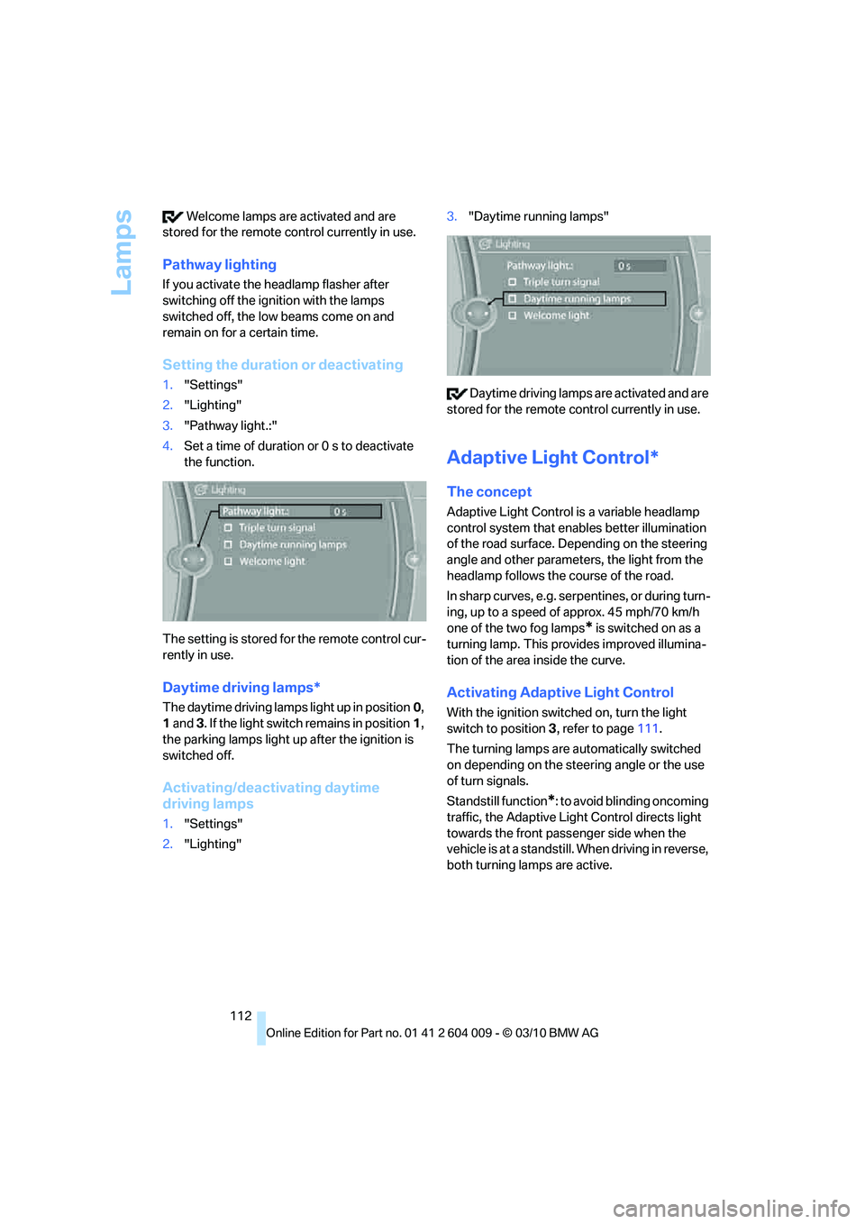
112 Welcome lamps are activated and are
stored for the remote control currently in use.
Pathway lighting
If you activate the headlamp flasher after
switching off the ignition with the lamps
switched off, the low beams come on and
remain on for a certain time.
Setting the duration or deactivating
1."Settings"
2."Lighting"
3."Pathway light.:"
4.Set a time of duration or 0 s to deactivate
the function.
The setting is stored for the remote control cur-
rently in use.
Daytime driving lamps*
The daytime driving lamps light up in position0,
1 and 3. If the light switch remains in position1,
the parking lamps light up after the ignition is
switched off.
Activating/deactivating daytime
driving lamps
1."Settings"
2."Lighting"3."Daytime running lamps"
Daytime driving lamps are activated and are
stored for the remote control currently in use.
Adaptive Light Control*
The concept
Adaptive Light Control is a variable headlamp
control system that enables better illumination
of the road surface. Depending on the steering
angle and other parameters, the light from the
headlamp follows the course of the road.
In sharp curves, e.g. serpentines, or during turn-
ing, up to a speed of approx. 45 mph/70 km/h
one of the two fog lamps
* is switched on as a
turning lamp. This provides improved illumina-
tion of the area inside the curve.
Activating Adaptive Light Control
With the ignition switched on, turn the light
switch to position 3, refer to page111.
The turning lamps are automatically switched
on depending on the steering angle or the use
of turn signals.
Standstill function
*: to avoid blinding oncoming
traffic, the Adaptive Light Control directs light
towards the front passenger side when the
vehicle is at a standstill. When driving in reverse,
both turning lamps are active.
Page 126 of 312
Practical interior accessories
124
Practical interior accessories
Integrated universal remote
control*
The concept
The integrated universal remote control can
replace as many as three hand-held transmit-
ters for various remote-controlled accessories,
such as garage and gate or lighting systems.
The integrated universal remote control regis-
ters and stores signals from the original hand-
held transmitters.
The signal of an original hand-held transmitter
can be programmed on one of the three mem-
ory buttons1. Then with the ignition switched
on, this programmed memory button1 can be
used to operate the respective feature. The
LED2 flashes to confirm transmission of the
signal.
Should you sell your vehicle one day, be sure to
delete the stored programs beforehand for your
safety, refer to page125.
To prevent possible damage or injury,
before programming or using the inte-
grated universal remote control, always inspect
the immediate area to make certain that no peo-
ple, animals or objects are within the travel
range of the device. Also, comply with the
safety precautions of the original hand-held
transmitter.<
Checking compatibility
If you see this symbol on the packaging
or in the manual supplied with the orig-
inal hand-held transmitter, it is safe to
assume that it is compatible with the integrated
universal remote control.
Should you have additional questions,
please contact your BMW Sports Activity
Vehicle Center or call: 1-800-355-3515.
Information is also provided on the Internet at:
www.bmwusa.com or
www.homelink.com.HomeLink is a registered trademark of Johnson
Controls, Inc.<
Programming
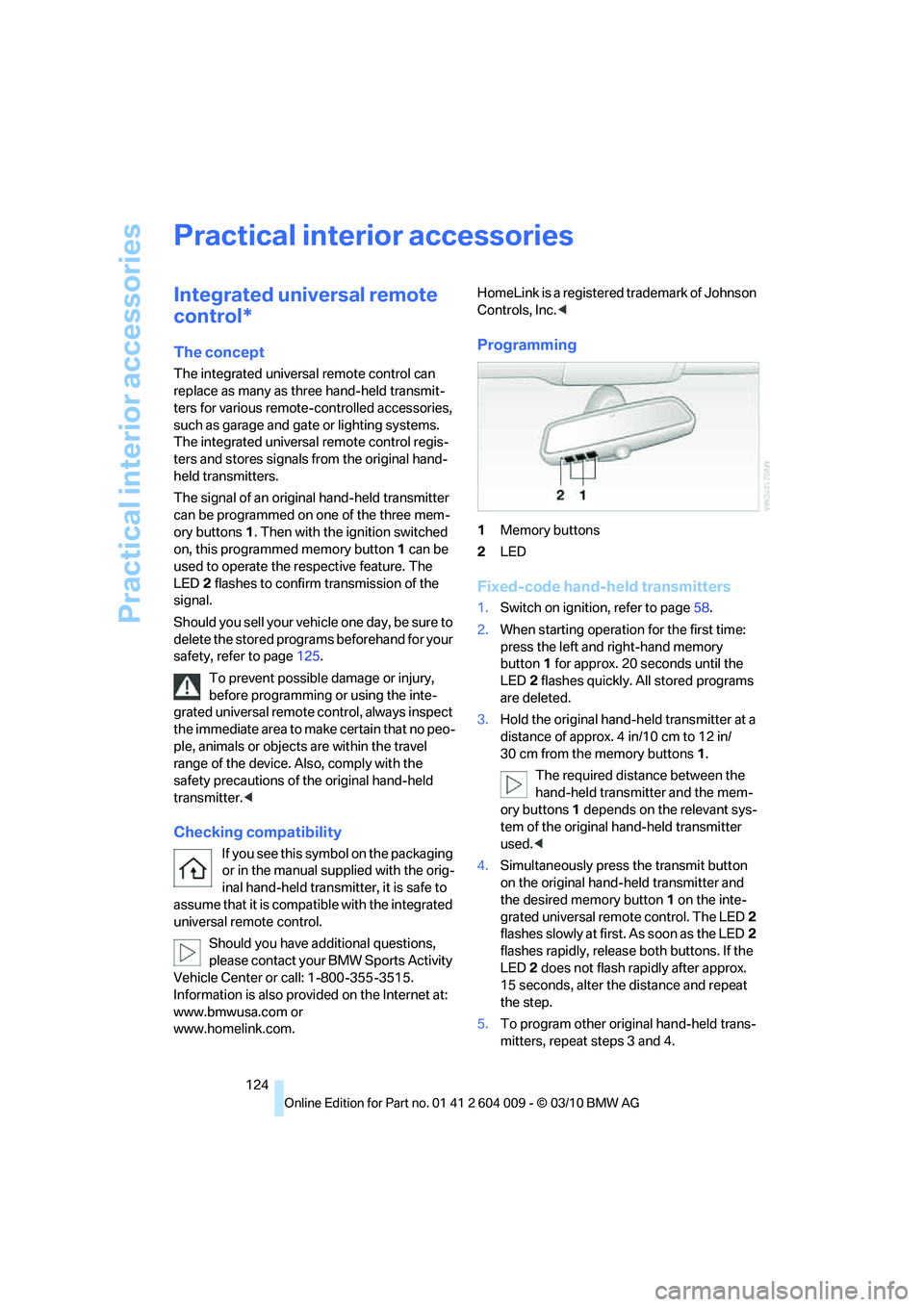
1Memory buttons
2LED
Fixed-code hand-held transmitters
1.Switch on ignition, refer to page58.
2.When starting operation for the first time:
press the left and right-hand memory
button1 for approx. 20 seconds until the
LED2 flashes quickly. All stored programs
are deleted.
3.Hold the original hand-held transmitter at a
distance of approx. 4 in/10 cm to 12 in/
30 cm from the memory buttons1.
The required distance between the
hand-held transmitter and the mem-
ory buttons1 depends on the relevant sys-
tem of the original hand-held transmitter
used.<
4.Simultaneously press the transmit button
on the original hand-held transmitter and
the desired memory button1 on the inte-
grated universal remote control. The LED 2
flashes slowly at first. As soon as the LED2
flashes rapidly, release both buttons. If the
LED2 does not flash rapidly after approx.
15 seconds, alter the distance and repeat
the step.
5.To program other original hand-held trans-
mitters, repeat steps 3 and 4.
Page 127 of 312
Controls
125Reference
At a glance
Driving tips
Communications
Navigation
Entertainment
Mobility
The corresponding memory button1 is now
programmed with the signal of the original
hand-held transmitter.
You can operate the device when the engine is
running or when the ignition is switched on.
If the device cannot be used after
repeated programming, check whether
the original hand-held transmitter uses an alter-
nating-code system. To do so, either read the
instructions for the original hand-held transmit-
ter or hold down the programmed memory
button1 of the integrated universal remote
control. If the LED2 on the integrated universal
remote control flashes rapidly for a short time
and then remains lit for approx. 2 seconds, this
indicates that the original hand-held transmitter
uses an alternating-code system. In the case of
an alternating-code system, program the mem-
ory buttons1 as described at Alternating-code
hand-held transmitters.<
Alternating-code hand-held
transmitters
To program the integrated universal remote
control, consult the operating instructions for
the equipment to be set. You will find informa-
tion there on the possibilities for synchroniza-
tion.
When programming hand-held transmitters
that employ an alternating code, observe the
following supplementary instructions:
Programming will be easier with the aid of
a second person.<
1.Park your vehicle within the range of the
remote-controlled device.
2.Program the integrated universal remote
control as described above in the section
Fixed-code hand-held transmitters.
3.Locate the button on the receiver of the
device to be set, e.g. on the drive unit.
4.Press the button on the receiver of the
device to be set. After step 4, you have
approx. 30 seconds for step 5.
5.Press the programmed memory button1
of the integrated universal remote control
three times.The corresponding memory button1 is now
programmed with the signal of the original
hand-held transmitter.
Should you have questions, please con-
tact your BMW Sports Activity Vehicle
Center.<
Deleting all stored programs
Press the left and right-hand memory button1
for approx. 20 seconds until the LED2 flashes
quickly:
All stored programs are deleted.
Reassigning individual programs
1.Hold the original hand-held transmitter at a
distance of approx. 4 in/10 cm to 12 in/
30 cm from the memory buttons1.
The required distance between the
hand-held transmitter and the mem-
ory buttons1 depends on the relevant sys-
tem of the original hand-held transmitter
used.<
2.Press the desired memory button1 of the
integrated universal remote control.
3.When the LED2 flashes slowly after approx.
20 seconds, press the transmit button of
the original hand-held transmitter. Release
both buttons as soon as the LED2 flashes
rapidly. If the LED2 does not flash rapidly
after approx. 15 seconds, alter the distance
and repeat the step.
Digital compass*
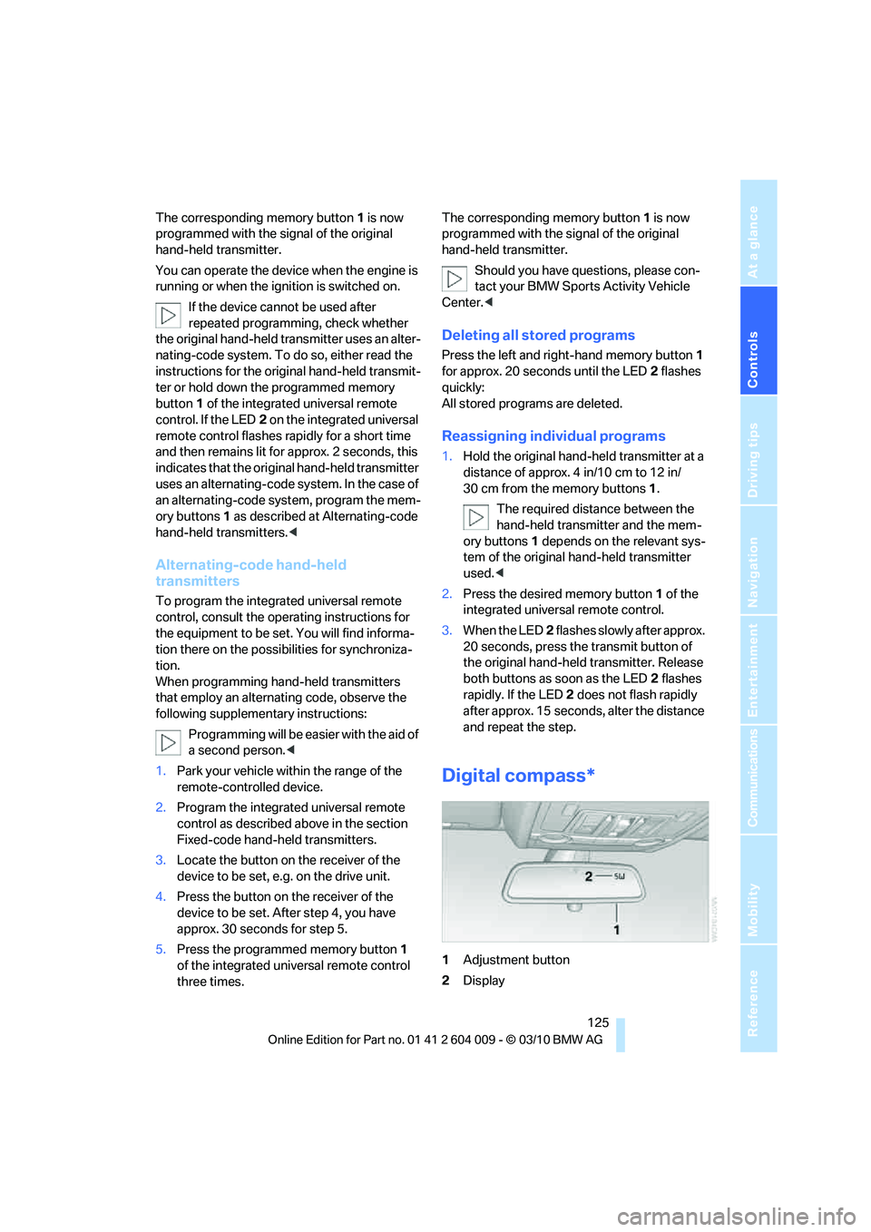
1Adjustment button
2Display