2011 BMW 550I SEDAN tow
[x] Cancel search: towPage 92 of 304
▷
When braking hard.
▷ When using the turn signal.
System limits Personal responsibility
The system cannot serve as a substitute
for
the driver's personal judgment of the course
of the road and the traffic situation.
In the event of a warning, do not jerk the steering
wheel, as you may lose control of the vehicle.◀
The system may not be fully functional in the
following situations:
▷ In heavy fog, rain or snowfall.
▷ In the event of worn, poorly visible, merging,
diverging,
or multiple lane markings such as
in construction areas.
▷ When lane markings are covered in snow,
ice, dirt or water.
▷ In tight curves or on narrow lanes.
▷ When the lane markings are covered by ob‐
jects.
▷ When driving very close to the vehicle in
front of you.
▷ When driving toward bright lights.
▷ When the windshield in front of the interior
rearview mirror is fogged over, dirty or cov‐
ered with stickers, etc.
Malfunctions
Steering wheel vibration
Frequent
activation of the steering wheel vibra‐
tion causes the system to overheat.
This causes the lane departure warning to be‐
come deactivated.
Let the system cool and reactivate it by pressing
the button. Camera
The camera is located on the front of the interior
rearview mirror.
Keep the area in front of the interior rearview
mirror clear.
Active Blind Spot Detection
*
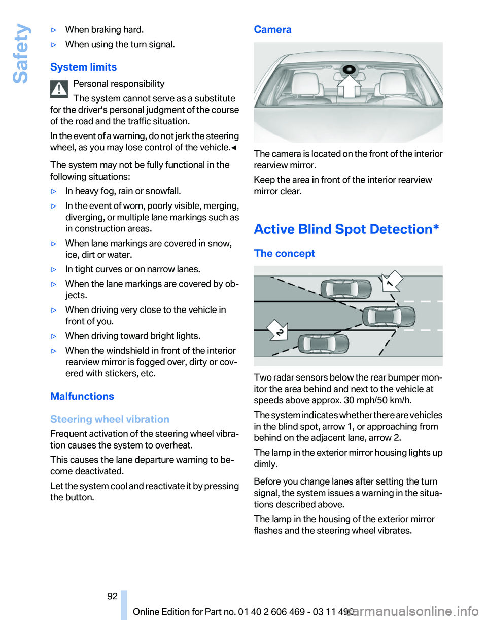
The concept Two radar sensors below the rear bumper mon‐
itor the area behind and next to the vehicle at
speeds above approx. 30 mph/50 km/h.
The
system indicates whether there are vehicles
in the blind spot, arrow 1, or approaching from
behind on the adjacent lane, arrow 2.
The lamp in the exterior mirror housing lights up
dimly.
Before you change lanes after setting the turn
signal, the system issues a warning in the situa‐
tions described above.
The lamp in the housing of the exterior mirror
flashes and the steering wheel vibrates.
Seite 92
92 Online Edition for Part no. 01 40 2 606 469 - 03 11 490
Safety
Page 108 of 304
Collision warning with
braking function*
The concept
The system issues a two-phase warning of a
danger of collision at speeds above approx.
10 mph/15 km/h.
The collision warning is available even if cruise
control has been deactivated.
It responds to stationary or moving objects that
are within the detection range of the radar sys‐
tem.
When the vehicle is intentionally brought into
contact with an object, the collision warning is
delayed to avoid false warnings.
Warning stages
Prewarning
This
warning is issued, for example, when there
is the impending danger of a collision or the dis‐
tance to the vehicle ahead is too small.
Acute warning with braking function
Warning of the imminent danger of a collision
when the vehicle approaches another object at
a relatively high differential speed.
The acute warning prompts the driver to inter‐
vene and, if there is the danger of a collision, is
accompanied by a braking intervention.
The braking intervention is executed with lim‐
ited braking force and for a brief period only. The
intervention cannot bring the vehicle to a com‐
plete standstill. The braking intervention is executed only if DSC
Dynamic Stability Control, refer to page
95, is
switched on.
Adapting your speed and driving style
The acute warning does not relieve the
driver of the responsibility to adapt his or her
driving speed and style to the traffic condi‐
tions.◀
The braking intervention can be interrupted by
pressing on the accelerator or by actively mov‐
ing the steering wheel.
When
towing or tow-starting the vehicle, switch
off the collision warning with braking function to
prevent undesired interventions.
The braking function is deactivated if the DSC
Dynamic Stability Control or DTC Dynamic
Traction Control is deactivated.
Switching the warning function on/off Press the button
▷ On: the LED lights up.
▷ Off: the LED goes out.
The state is stored for the remote control cur‐
rently in use.
Configuring the prewarning
After the warning function is switched on, the
following can be set via the iDrive:
▷ The prewarning can be switched on/off.
▷ The time of the prewarning can be set.
These settings have no effect on the time of the
warning from the Active Cruise Control* that
prompts the driver to intervene or brake. Seite 108
108 Online Edition for Part no. 01 40 2 606 469 - 03 11 490
Driving comfort
Page 111 of 304
Resuming the desired speed
Press the button.
The stored speed is reached and maintained.
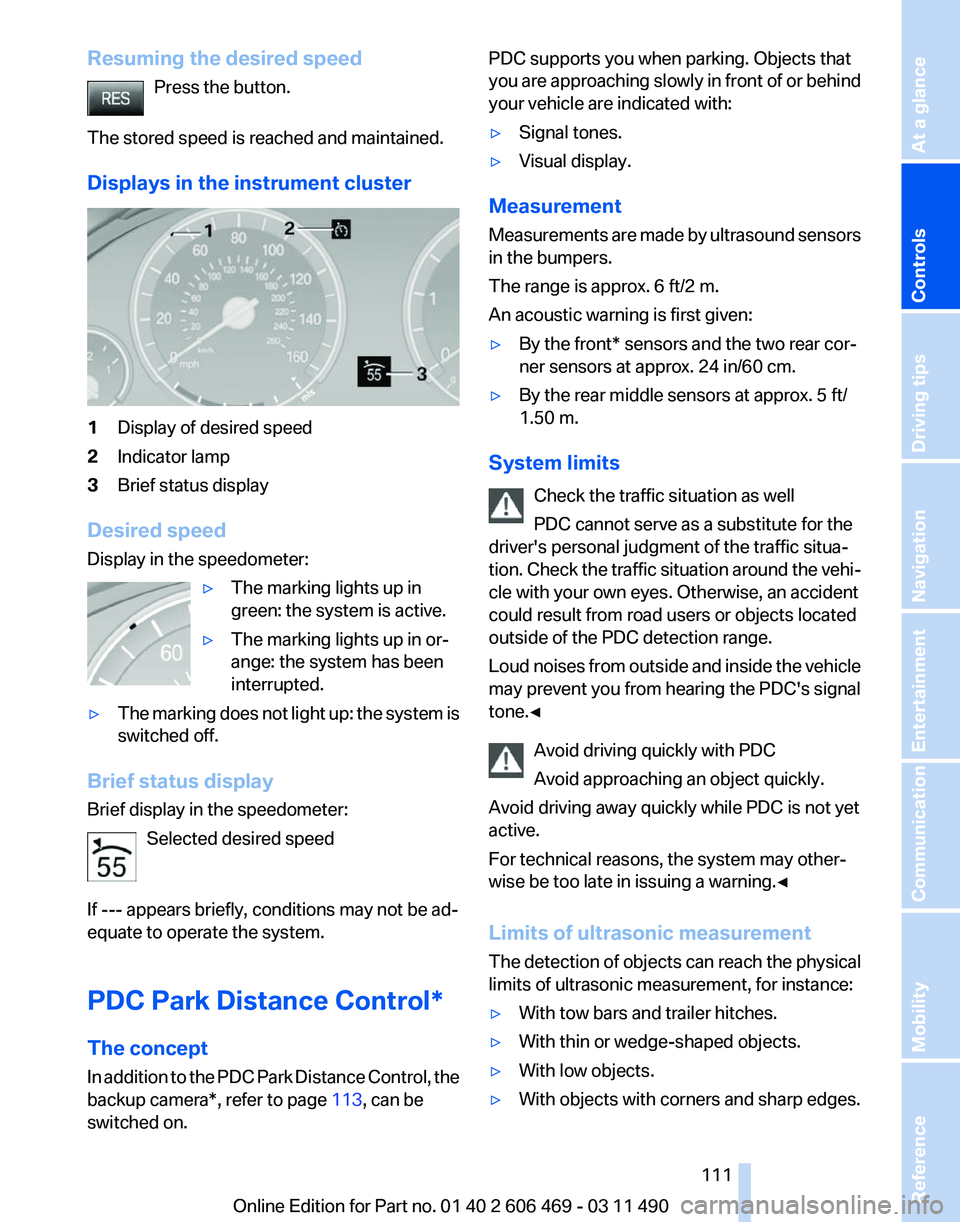
Displays in the instrument cluster 1
Display of desired speed
2 Indicator lamp
3 Brief status display
Desired speed
Display in the speedometer: ▷The marking lights up in
green: the system is active.
▷ The marking lights up in or‐
ange: the system has been
interrupted.
▷ The marking does not light up: the system is
switched off.
Brief status display
Brief display in the speedometer: Selected desired speed
If --- appears briefly, conditions may not be ad‐
equate to operate the system.
PDC Park Distance Control*
The concept
In
addition to the PDC Park Distance Control, the
backup camera*, refer to page 113, can be
switched on. PDC supports you when parking. Objects that
you
are approaching slowly in front of or behind
your vehicle are indicated with:
▷ Signal tones.
▷ Visual display.
Measurement
Measurements
are made by ultrasound sensors
in the bumpers.
The range is approx. 6 ft/2 m.
An acoustic warning is first given:
▷ By the front* sensors and the two rear cor‐
ner sensors at approx. 24 in/60 cm.
▷ By the rear middle sensors at approx. 5 ft/
1.50 m.
System limits Check the traffic situation as well
PDC cannot serve as a substitute for the
driver's personal judgment of the traffic situa‐
tion.
Check the traffic situation around the vehi‐
cle with your own eyes. Otherwise, an accident
could result from road users or objects located
outside of the PDC detection range.
Loud noises from outside and inside the vehicle
may prevent you from hearing the PDC's signal
tone.◀
Avoid driving quickly with PDC
Avoid approaching an object quickly.
Avoid driving away quickly while PDC is not yet
active.
For technical reasons, the system may other‐
wise be too late in issuing a warning.◀
Limits of ultrasonic measurement
The detection of objects can reach the physical
limits of ultrasonic measurement, for instance:
▷ With tow bars and trailer hitches.
▷ With thin or wedge-shaped objects.
▷ With low objects.
▷ With objects with corners and sharp edges. Seite 111
111Online Edition for Part no. 01 40 2 606 469 - 03 11 490
Reference Mobility Communication Entertainment Navigation Driving tips
Controls At a glance
Page 121 of 304
▷
If the vehicle speed exceeds approx. 6 mph/
10 km/h.
▷ On snow-covered or slippery road surfaces
if necessary.
▷ If doors are open.
A Check Control message is displayed.
Continuing
An interrupted parking procedure can be con‐
tinued if necessary.
Follow
the instructions on the Control Display to
do this.
Switching off
The system can be deactivated as follows:
▷ Press the button. ▷
Switch off the ignition.
Malfunction
A Check Control message is displayed.
The parking assistant failed. Have the system
checked.
System limits Changes to the parking space
Changes to the parking space after it was
measured
are not taken into account by the sys‐
tem.
Therefore, always be alert and ready to inter‐
vene; otherwise, there is the danger of an acci‐
dent occurring.◀
Transporting loads
Loads that extend beyond the perimeter
of the vehicle are not taken into account by the
system during the parking procedure.
Therefore, always be alert and ready to inter‐
vene; otherwise, there is the danger of an acci‐
dent occurring.◀
Curbs
The parking assistant may steer the vehi‐
cle over or onto curbs. Therefore, always be alert and ready to inter‐
vene;
otherwise, the wheels, tires, or the vehicle
may become damaged.◀
No parking assistance
The parking assistant does not provide assis‐
tance in parking.
▷ In tight curves.
Functional limitations
The system may not be fully functional in the
following situations:
▷ When sensors are dirty or iced over.
▷ In heavy fog, rain or snowfall.
▷ On bumpy road surfaces such as gravel
roads.
▷ When leaves or snow has collected in the
parking space.
Limits of ultrasonic measurement
The
detection of objects can reach the physical
limits of ultrasonic measurement, for instance:
▷ With tow bars and trailer hitches.
▷ With thin or wedge-shaped objects.
▷ With elevated, protruding objects such as
ledges or cargo.
▷ With objects with corners and sharp edges.
▷ With objects with a fine surface structure,
such as fences.
The parking assistant may identify parking
spaces that are not suitable for parking.
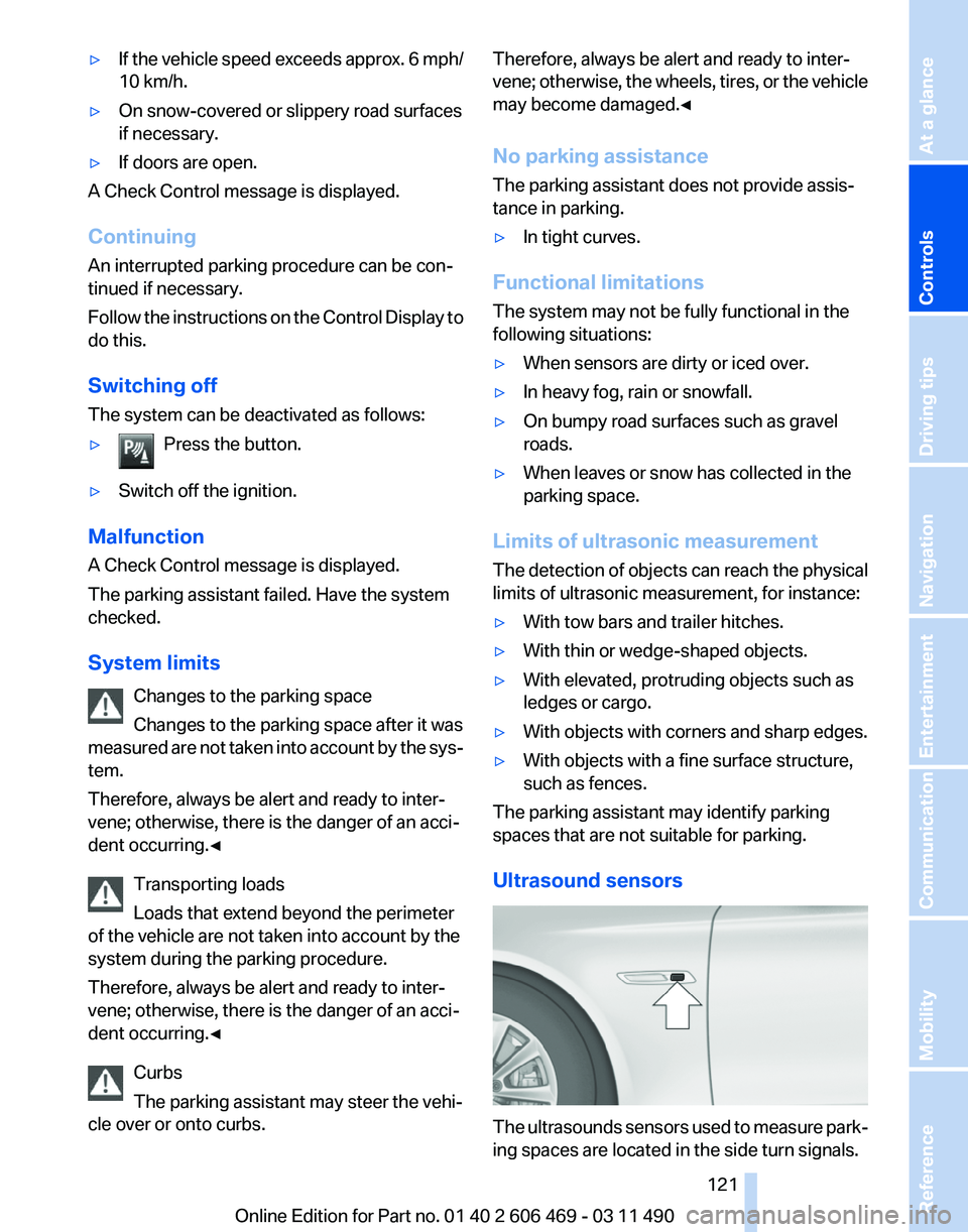
Ultrasound sensors The ultrasounds sensors used to measure park‐
ing spaces are located in the side turn signals.
Seite 121
121Online Edition for Part no. 01 40 2 606 469 - 03 11 490
Reference Mobility Communication Entertainment Navigation Driving tips
Controls At a glance
Page 129 of 304
Switching on
Press any button.
Microfilter/activated-charcoal filter
The microfilter removes dust and pollen from
the incoming air.
The activated-charcoal filter removes gaseous
pollutants from the outside air that enters the
vehicle.
This combined filter should be replaced during
scheduled
maintenance of your vehicle., refer to
page 260
Ventilation
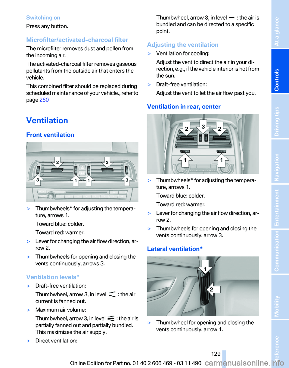
Front ventilation ▷
Thumbwheels* for adjusting the tempera‐
ture, arrows 1.
Toward blue: colder.
Toward red: warmer.
▷ Lever for changing the air flow direction, ar‐
row 2.
▷ Thumbwheels for opening and closing the
vents continuously, arrows 3.
Ventilation levels*
▷ Draft-free ventilation:
Thumbwheel, arrow 3, in level : the air
current is fanned out.
▷ Maximum air volume:
Thumbwheel,
arrow 3, in level : the air is
partially fanned out and partially bundled.
This maximizes the air supply.
▷ Direct ventilation: Thumbwheel, arrow 3, in level :
the air is
bundled and can be directed to a specific
point.
Adjusting the ventilation
▷ Ventilation for cooling:
Adjust the vent to direct the air in your di‐
rection,
e.g., if the vehicle interior is hot from
the sun.
▷ Draft-free ventilation:
Adjust the vent to let the air flow past you.
Ventilation in rear, center ▷
Thumbwheels* for adjusting the tempera‐
ture, arrows 1.
Toward blue: colder.
Toward red: warmer.
▷ Lever for changing the air flow direction, ar‐
row 2.
▷ Thumbwheels for opening and closing the
vents continuously, arrow 3.
Lateral ventilation* ▷
Thumbwheel for opening and closing the
vents continuously, arrow 1.
Seite 129
129Online Edition for Part no. 01 40 2 606 469 - 03 11 490
Reference Mobility Communication Entertainment Navigation Driving tips
Controls At a glance
Page 149 of 304
hicle and unstable driving situations may
result.
2. Determine the combined weight of the
driver and passengers that will be riding in
your vehicle.
3. Subtract the combined weight of the driver
and
passengers from XXX kilograms or YYY
pounds.
4. The resulting figure equals the available
amount
of cargo and luggage load capacity.
For example, if the YYY amount equals
1,000 lbs and there will be four 150 lbs pas‐
sengers in your vehicle, the amount of avail‐
able cargo and luggage load capacity is
400 lbs: 1,000 lbs minus 600 lbs = 400 lbs.
5. Determine the combined weight of luggage
and
cargo being loaded on the vehicle. That
weight may not safely exceed the available
cargo and luggage load capacity calculated
in Step 4.
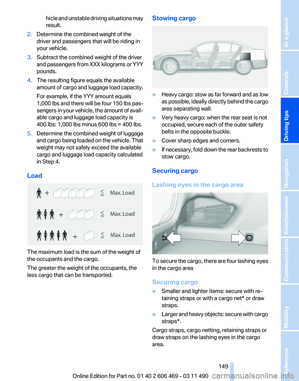
Load The maximum load is the sum of the weight of
the occupants and the cargo.
The greater the weight of the occupants, the
less cargo that can be transported. Stowing cargo ▷
Heavy cargo: stow as far forward and as low
as
possible, ideally directly behind the cargo
area separating wall.
▷ Very heavy cargo: when the rear seat is not
occupied, secure each of the outer safety
belts in the opposite buckle.
▷ Cover sharp edges and corners.
▷ If necessary, fold down the rear backrests to
stow cargo.
Securing cargo
Lashing eyes in the cargo area To secure the cargo, there are four lashing eyes
in the cargo area
Securing cargo
▷
Smaller and lighter items: secure with re‐
taining straps or with a
cargo net* or draw
straps.
▷ Larger and heavy objects: secure with cargo
straps*.
Cargo straps, cargo netting, retaining straps or
draw straps on the lashing eyes in the cargo
area.
Seite 149
149Online Edition for Part no. 01 40 2 606 469 - 03 11 490
Reference Mobility Communication Entertainment Navigation
Driving tips Controls At a glance
Page 154 of 304
Navigation*
Navigation system
General information
The navigation system can determine the pre‐
cise position of the vehicle, with the aid of sat‐
ellites and vehicle sensors, and can reliably
guide you to every entered destination.
Navigation
data are stored in the vehicle and can
be updated.
Entries in stationary vehicle
Enter data only when the vehicle is sta‐
tionary, and always give priority to the applicable
traffic regulations in the event of any contradic‐
tion between traffic and road conditions and the
instructions issued by the navigation system.
Failure to take to this precaution can place you
in violation of the law and put vehicle occupants
and other road users in danger.◀
Destination input
Manual destination entry
General information
The system supports you in entering street
names and house numbers by automatically
completing the entry and providing entry com‐
parisons, refer to page 21.
Stored town/city and street names can be called
up quickly.
▷ If the existing entries should not be changed,
the entries for the state/province and town/
city can be skipped.
▷ Destination guidance is started to the town/
city center if no street is entered.
Entering a state/province
1. Press the MENU button.
2. "Navigation" 3.
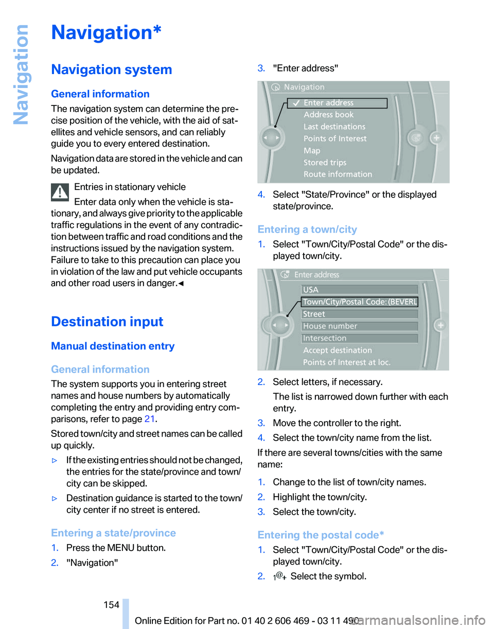
"Enter address" 4.
Select "State/Province" or the displayed
state/province.
Entering a town/city
1. Select "Town/City/Postal Code" or the dis‐
played town/city. 2.
Select letters, if necessary.
The list is narrowed down further with each
entry.
3. Move the controller to the right.
4. Select the town/city name from the list.
If there are several towns/cities with the same
name:
1. Change to the list of town/city names.
2. Highlight the town/city.
3. Select the town/city.
Entering the postal code*
1. Select "Town/City/Postal Code" or the dis‐
played town/city.
2. Select the symbol.
Seite 154
154 Online Edition for Part no. 01 40 2 606 469 - 03 11 490
Navigation
Page 155 of 304
3.
Select the numbers.
4. Change to the list of postal codes and towns/
cities.
5. Highlight the entry.
6. Selecting an entry.
Entering a street and intersection
1. Select "Street" or the displayed street.
2. Enter a street and intersection in the same
way as you would enter a town/city.
If there are several streets with the same name:
1. Change to the list of street names.
2. Highlight the street.
3. Select the street.
Alternative: enter the street address
and house number
1. Select "Street" or the displayed street.
2. Enter the street as you would the town/city.
3. "House number"
4. Select the numbers.
5. Change to the list of house numbers.
6. Select a house number or range of house
numbers.
Street does not exist in the destination
city/town
The
desired street does not exist in the specified
city/town because it belongs to another part of
the city/town.
1. "Navigation"
2. "Enter address"
3. Select "Street" or the displayed street.
4. Change to the list of street names.
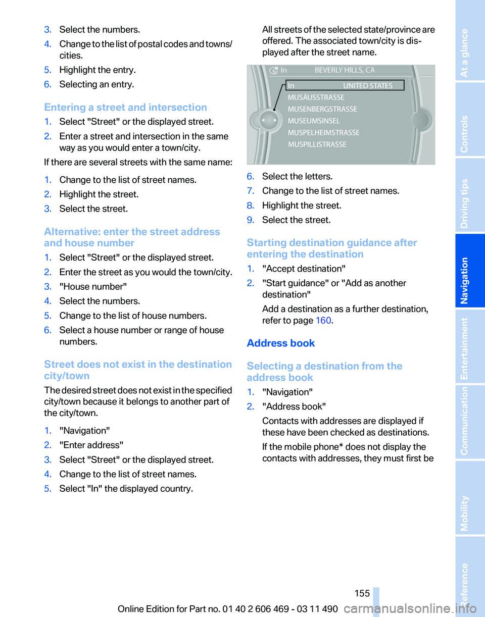
5. Select "In" the displayed country. All streets of the selected state/province are
offered. The associated town/city is dis‐
played after the street name.
6.
Select the letters.
7. Change to the list of street names.
8. Highlight the street.
9. Select the street.
Starting destination guidance after
entering the destination
1. "Accept destination"
2. "Start guidance" or "Add as another
destination"
Add a destination as a further destination,
refer to page 160.
Address book
Selecting a destination from the
address book
1. "Navigation"
2. "Address book"
Contacts with addresses are displayed if
these have been checked as destinations.
If the mobile phone* does not display the
contacts with addresses, they must first be
Seite 155
155Online Edition for Part no. 01 40 2 606 469 - 03 11 490
Reference Mobility Communication Entertainment
Navigation Driving tips Controls At a glance