2011 BMW 550I lock
[x] Cancel search: lockPage 41 of 304
Closing without the pinch protection
system
Danger of pinching
Monitor the closing process and make
sure
that the closing path of the window is clear;
otherwise, injuries may result.◀
For example, if there is an external danger or if
ice on the windows prevents a window from
closing normally, proceed as follows:
1. Pull the switch past the resistance point and
hold it there.
Pinch protection is limited and the window
reopens
slightly if the closing force exceeds
a certain value.
2. Pull the switch past the resistance point
again within approx. 4 seconds and hold it
there.
The window closes without pinch protec‐
tion.
Safety switch
The safety switch in the driver's door can be
used to prevent children, for example, from
opening
and closing the rear windows using the
switches in the rear.
Switching on and off
Press the button.
The LED lights up if the safety function
is switched on.
Safety switch for rear operation
Press the safety switch when transporting
children in the rear; otherwise, injury may result
if the windows are closed without supervision.◀
Roller sunblinds*
General information
If you are no longer able to move the roller sun‐
blind for the rear window after having activated
it a number of times in a row, the system is blocked for a limited time to prevent overheat‐
ing. Let the system cool.
The roller sunblind for the rear window cannot
be moved at low interior temperatures.
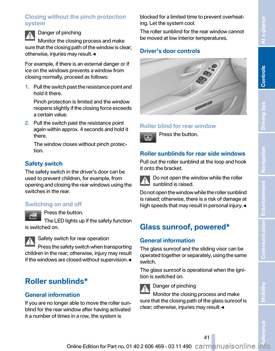
Driver's door controls
Roller blind for rear window
Press the button.
Roller sunblinds for rear side windows
Pull out the roller sunblind at the loop and hook
it onto the bracket. Do not open the window while the roller
sunblind is raised.
Do
not open the window while the roller sunblind
is raised; otherwise, there is a risk of damage at
high speeds that may result in personal injury.◀
Glass sunroof, powered*
General information
The glass sunroof and the sliding visor can be
operated together or separately, using the same
switch.
The glass sunroof is operational when the igni‐
tion is switched on.
Danger of pinching
Monitor the closing process and make
sure that the closing path of the glass sunroof is
clear; otherwise, injuries may result.◀ Seite 41
41Online Edition for Part no. 01 40 2 606 469 - 03 11 490
Reference Mobility Communication Entertainment Navigation Driving tips
Controls At a glance
Page 44 of 304
Adjusting
Sitting safely
The
ideal seating position can make a vital con‐
tribution to relaxed, fatigue-free driving.
The seating position plays an important role in
an accident in combination with:
▷ Safety belts, refer to page 48.
▷ Head restraints, refer to page 49.
▷ Airbags, refer to page 85.
Seats
Adjusting
General information Do not adjust the seat while driving
Never attempt to adjust the driver's seat
while driving.
The
seat could respond with unexpected move‐
ment and the ensuing loss of vehicle control
could lead to an accident.◀
Do not incline the backrest too far to the
rear
Do not incline the backrest on the front passen‐
ger side too far to the rear during driving. Oth‐
erwise, there is the danger of sliding under the
safety belt in an accident. This would eliminate
the protection normally provided by the belt.◀
The seat setting is stored for the remote control
currently in use. When the vehicle is unlocked
via the remote control, the position is automati‐
cally retrieved if this function, refer to page 33,
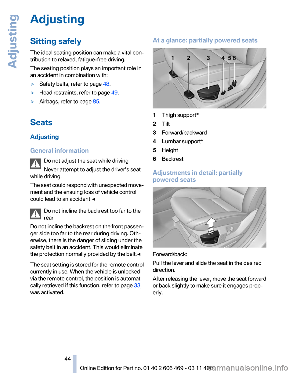
was activated. At a glance: partially powered seats
1
Thigh support*
2 Tilt
3 Forward/backward
4 Lumbar support*
5 Height
6 Backrest
Adjustments in detail: partially
powered seats Forward/back:
Pull the lever and slide the seat in the desired
direction.
After
releasing the lever, move the seat forward
or back slightly to make sure it engages prop‐
erly.
Seite 44
44 Online Edition for Part no. 01 40 2 606 469 - 03 11 490
Adjusting
Page 52 of 304
General information
The
mirror on the passenger side is more curved
than the driver's side mirror.
Estimating distances correctly
Objects reflected in the mirror are closer
than they appear. Do not estimate the distance
to the traffic behind you based on what you see
in the mirror, as this will increase your risk of an
accident.◀
The mirror setting is stored for the remote con‐
trol currently in use. When the vehicle is un‐
locked via the remote control, the position is au‐
tomatically retrieved if the setting for this
function is active.
Selecting a mirror
To change over to the other mirror:
Slide the mirror changeover switch.
Adjusting electrically The setting corresponds to the direction
in which the button is pressed.
Storing positions*
Seat, mirror, and steering wheel memory, refer
to page 51.
Adjusting manually
If an electrical malfunction occurs, for example,
press the edges of the mirror glass.
Automatic Curb Monitor*
When the reverse gear is engaged, the mirror
glass tilts downward slightly on the front pas‐
senger side. This improves your view of the curb
and other low-lying obstacles when parking, for
example.
Activating
1. Slide the mirror changeover switch
to the driver's side mirror position.
2. Engage transmission position R. Deactivating
Slide the mirror changeover switch to the pas‐
senger's side mirror position.
Fold in and out*
Press the button.
Possible up to approx. 15 mph/20 km/h.
For example, this is advantageous
▷ In car washes.
▷ In narrow streets.
▷ For folding back mirrors that were folded
away manually.
Mirrors that were folded in are folded out auto‐
matically
at a speed of approx. 25 mph/40 km/h.
Fold in the mirror in a car wash
Before entering an automatic car wash,
fold in the exterior mirrors by hand or with the
button; otherwise, they could be damaged, de‐
pending on the width of the vehicle.◀
Automatic heating
Both exterior mirrors are automatically heated
whenever the engine is running.
Automatic dimming feature
Both exterior mirrors are automatically dimmed.
Photocells are used for control in the Interior rear
view mirror, refer to page 53.
Interior rearview mirror
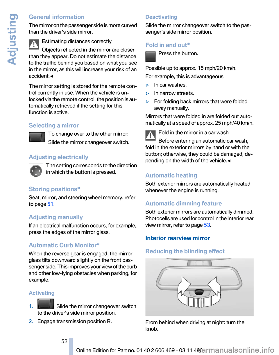
Reducing the blinding effect From behind when driving at night: turn the
knob. Seite 52
52 Online Edition for Part no. 01 40 2 606 469 - 03 11 490
Adjusting
Page 55 of 304
Backrest width*
Before
installing a child restraint fixing system in
the front passenger seat, open the backrest
width completely. Do not change the backrest
width again and do not call up a memory posi‐
tion.
Backrest width for the child seat
Before installing a child restraint fixing
system in the front passenger seat, the backrest
width must be opened completely. Do not
change the adjustment after this; otherwise, the
stability of the child seat will be reduced.◀
Child seat security The rear safety belts and the front passenger
safety belt can be locked against pulling out for
mounting the child restraint fixing systems.
Locking the safety belt
1.
Pull out the belt webbing completely.
2. Secure the child restraint fixing system with
the belt.
3. Allow the belt webbing to be pulled in and
pull it taut against the child restraint fixing
system. The safety belt is locked.
Unlocking the safety belt
1. Unbuckle the belt buckle.
2. Remove the child restraint fixing system.
3. Allow the belt webbing to be pulled in com‐
pletely. LATCH child restraint fixing
system
LATCH: Lower Anchors and Tether for CHil‐
dren.
Note
Manufacturer's information for LATCH
child restraint fixing systems
To
mount and use the LATCH child restraint fix‐
ing systems, observe the operating and safety
information from the system manufacturer; oth‐
erwise, the level of protection may be reduced.◀
Mounts for the lower LATCH anchors
Correctly engage the lower LATCH an‐
chors
Make sure that the lower LATCH anchors have
properly engaged and that the child restraint fix‐
ing system is resting snugly against the back‐
rest; otherwise, the degree of protection offered
may be reduced.◀
Before mounting the LATCH child restraint fix‐
ing system, pull the belt away from the child re‐
straint fixing system.
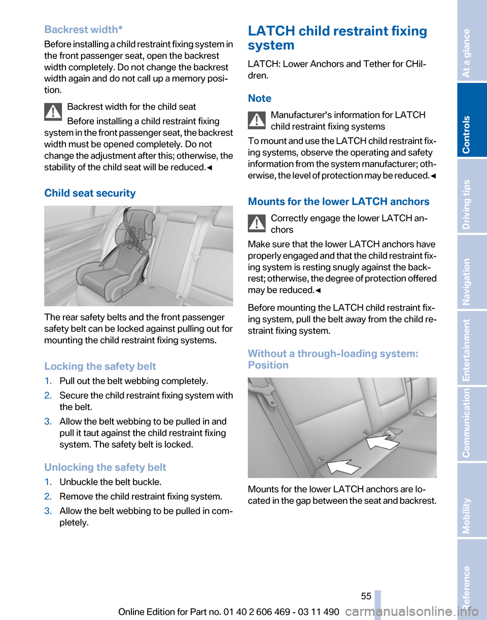
Without a through-loading system:
Position Mounts for the lower LATCH anchors are lo‐
cated
in the gap between the seat and backrest. Seite 55
55Online Edition for Part no. 01 40 2 606 469 - 03 11 490
Reference Mobility Communication Entertainment Navigation Driving tips
Controls At a glance
Page 57 of 304
Locking the doors and
windows
Rear doors
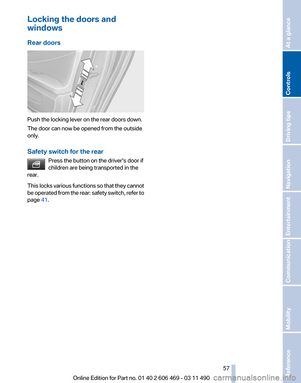
Push the locking lever on the rear doors down.
The door can now be opened from the outside
only.
Safety switch for the rear
Press the button on the driver's door if
children are being transported in the
rear.
This
locks various functions so that they cannot
be operated from the rear: safety switch, refer to
page 41. Seite 57
57Online Edition for Part no. 01 40 2 606 469 - 03 11 490
Reference Mobility Communication Entertainment Navigation Driving tips
Controls At a glance
Page 58 of 304
Driving
Start/Stop button
The concept
Pressing the Start/Stop button
switches
the ignition on or off and
starts the engine.
Automatic transmission*: the en‐
gine starts if the brake is de‐
pressed when the Start/Stop button is pressed.
Manual transmission: the engine starts if the
clutch is depressed when the Start/Stop button
is pressed.
Ignition on
Automatic transmission*: press the Start/Stop
button, and do not press on the brake pedal at
the same time.
Manual-shift transmission: press the Start/Stop
button, and do not press on the clutch pedal at
the same time.
All vehicle systems are ready for operation.
Most of the indicator and warning lamps in the
instrument cluster light up for varying lengths of
time.
To save battery power when the engine is off,
switch off the ignition and any unnecessary
electronic systems/power consumers.
The ignition switches off automatically:
▷ When the vehicle is locked, if the low beams
are switched on.
▷ Shortly before the battery is discharged
completely, so that the engine can still be
started.
▷ If the engine is switched off and the ignition
is switched on, the system automatically
switches to the radio ready state when the
door is opened if the lights are switched off
or the daytime running lights are switched
on. Ignition off
Automatic transmission*: press the Start/Stop
button again, and do not press on the brake
pedal at the same time.
Manual-shift
transmission: press the Start/Stop
button again, and do not press on the clutch
pedal at the same time.
All indicator lamps in the instrument cluster go
out.
To save battery power when the engine is off,
switch off the ignition and any unnecessary
electronic systems/power consumers.
Transmission position P with the ignition
off
When the ignition is switched off, position P is
engaged automatically. When in an automatic
car wash, for example, ensure that the ignition is
not switched off accidentally.◀
When the vehicle is locked using the central
locking system, the ignition switches off auto‐
matically.
Radio ready state
Activate radio ready state:
▷ When the ignition is switched off: press ON/
OFF button on the radio.
▷ When the engine is running: press START/
STOP button.
Some electronic systems/power consumers re‐
main ready for operation.
Radio ready state switches off automatically:
▷ After approx. 8 minutes.
▷ When the vehicle is locked using the central
locking system. Seite 58
58 Online Edition for Part no. 01 40 2 606 469 - 03 11 490
Driving
Page 65 of 304

Automatic transmission with
Steptronic*
Transmission positions
D Drive, automatic position
Position for normal vehicle operation. All for‐
ward gears are available.
R is Reverse
Select only when the vehicle is stationary.
N is Neutral
Use in automatic car washes, for example. The
vehicle can roll.
When the ignition is switched off, refer to
page
58, position P is engaged automatically.
P Park
Select only when the vehicle is stationary. The
drive wheels are blocked.
P is engaged automatically:
▷ After the engine is switched off, if the car is
in
radio ready state, refer to page 58, or if the
ignition is switched off, refer to page 58, and
if position R or D is engaged.
▷ If the ignition is switched off and position N
is engaged.
▷ If the safety belt is unbuckled, the driver's
door is opened, and the brake pedal is not
pressed while the vehicle is stationary and
transmission position R or D is engaged.
Kickdown
Kickdown is used to achieve maximum driving
performance. Press on the accelerator beyond
the resistance point at the full throttle position.
Engaging the transmission position
▷ Transmission position P can only be disen‐
gaged
if the engine is running and the brake
pedal is pressed.
▷ With the vehicle stationary, press on the
brake pedal before shifting out of P or N; otherwise, the shift command will not be
executed: shift lock.
Depress
the brake until you start driv‐
ing
To prevent the vehicle from creeping after
you select a driving position, maintain pres‐
sure on the brake pedal until you are ready
to start.◀ Engaging D, R and N
Briefly push the selector lever in the desired di‐
rection, beyond a resistance point if necessary.
After
releasing the selector lever, it returns to its
center position. Press the Unlock button to:
▷
Engage R.
▷ Shift out of P.
Seite 65
65Online Edition for Part no. 01 40 2 606 469 - 03 11 490
Reference Mobility Communication Entertainment Navigation Driving tips
Controls At a glance
Page 71 of 304

Overview: indicator/warning lamps
Symbol Function or system
Turn signal
Parking brake
Parking brake in Canadian models
Automatic Hold*
Front fog lamps*
High beams
High-beam Assistant*
Parking lamps, headlamp control
Active Cruise Control*
Vehicle detection, Active Cruise
Control*
Cruise control*
Lane departure warning*
DSC Dynamic Stability Control
DSC Dynamic Stability Control or
DTC Dynamic Traction Control
Tire Pressure Monitor* Symbol Function or system
Safety belts
Airbag system
Steering system
Emissions
Brake system
Brake system in Canadian models
Antilock Brake System ABS
Antilock Brake System ABS in Cana‐
dian models
Text messages
Text
messages in combination with a symbol in
the instrument cluster explain a Check Control
message and the meaning of the indicator and
warning lamps.
Supplementary text messages
Addition information, such as on the cause of a
fault or the required action, can be called up via
Check Control. The supplementary text of ur‐
gent messages is displayed automatically.
It is shown on the Control Display.
Symbols
Depending on the Check Control message, the
following functions can be selected.
▷ "Owner's Manual"
Display additional information about the
Check Control message in the integrated
owner's manual.
Seite 71
71Online Edition for Part no. 01 40 2 606 469 - 03 11 490
Reference Mobility Communication Entertainment Navigation Driving tips
Controls At a glance