2011 BMW 528I rear seat entertainment
[x] Cancel search: rear seat entertainmentPage 47 of 304

Front seat heating*
Switching on
Press the button once for each temper‐
ature level.
The maximum temperature is reached when
three LEDs are lit.
Switching off
Press the button longer.
The LEDs go out.
The temperature may be reduced or seat heat‐
ing may be switched off entirely to save battery
power.
Temperature distribution*
The heating action in the seat cushion and back‐
rest can be distributed in different ways.
1. "Climate"
2. "Seat heating distribution"
3. Select the required seat. 4.
Turn the controller to set the temperature
distribution. Rear seat heating*
Switching on
Press the button once for each temper‐
ature level.
The maximum temperature is reached when
three LEDs are lit.
Switching off
Press the button longer.
The LEDs go out.
Front active seat ventilation*
The seat cushion and backrest surfaces are
cooled by means of integrated fans.
The ventilation rapidly cools the seat, e.g., if the
vehicle interior is overheated or for continuous
cooling at high temperatures. Switching on
Press
the button once for each ventila‐
tion level.
The highest level is active when three LEDs are
lit. Seite 47
47Online Edition for Part no. 01 40 2 606 469 - 03 11 490
Reference Mobility Communication Entertainment Navigation Driving tips
Controls At a glance
Page 49 of 304
Checking and replacing safety belts
Have the work performed only by your
service center; otherwise, it cannot be ensured
that this safety feature will function properly.◀
Front head restraints
Correctly adjusted head restraint
A correctly adjusted head restraint reduces the
risk
of injury to cervical vertebrae in the event of
an accident.
Adjusting the head restraint
Correctly adjust the head restraints of all
occupied seats; otherwise, there is an increased
risk of injury in an accident.◀
Height
Adjust the head restraint so that its center is ap‐
proximately at ear level.
Distance
Adjust the distance so that the head restraint is
as close as possible to the back of the head.
Active head restraint
In the event of a rear-end collision with a certain
severity, the active head restraint automatically
reduces the distance from the head.
Reduced protective function
▷Do not use seat or head restraint cov‐
ers.
▷ Do not hang objects, e.g., clothes hangers,
on the head restraints.
▷ Only attach accessories approved by BMW
to the seat or head restraint.
Otherwise, the protective function of the active
head
restraint will be impaired and the personal
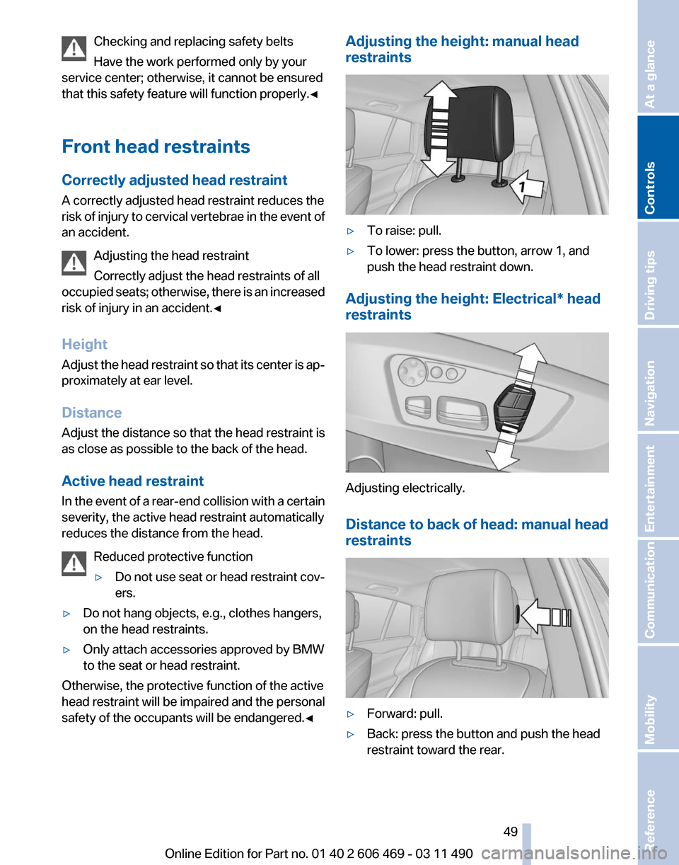
safety of the occupants will be endangered.◀ Adjusting the height: manual head
restraints
▷
To raise: pull.
▷ To lower: press the button, arrow 1, and
push the head restraint down.
Adjusting the height: Electrical* head
restraints Adjusting electrically.
Distance to back of head: manual head
restraints
▷
Forward: pull.
▷ Back: press the button and push the head
restraint toward the rear.
Seite 49
49Online Edition for Part no. 01 40 2 606 469 - 03 11 490
Reference Mobility Communication Entertainment Navigation Driving tips
Controls At a glance
Page 53 of 304

Interior rearview mirror, automatic
dimming feature
*Photocells are used for control:
▷
In the mirror glass.
▷ On the back of the mirror.
For proper operation:
▷ Keep the photocells clean.
▷ Do not cover the area between the inside
rearview mirror and the windshield.
Steering wheel
General information Do not adjust while driving
Do not adjust the steering wheel while
driving; otherwise, an unexpected movement
could result in an accident.◀
Manual steering wheel adjustment 1.
Fold the lever down.
2. Move the steering wheel to the preferred
height and angle to suit your seating posi‐
tion.
3. Fold the lever back. Power* steering wheel adjustment
The steering wheel can be adjusted in four di‐
rections.
Storing the position
Seat, mirror, and steering wheel memory, refer
to page
51.
Steering wheel heating
*
Switching on/off Press the button.
▷ On: the LED lights up.
▷ Off: the LED goes out. Seite 53
53Online Edition for Part no. 01 40 2 606 469 - 03 11 490
Reference Mobility Communication Entertainment Navigation Driving tips
Controls At a glance
Page 55 of 304
Backrest width*
Before
installing a child restraint fixing system in
the front passenger seat, open the backrest
width completely. Do not change the backrest
width again and do not call up a memory posi‐
tion.
Backrest width for the child seat
Before installing a child restraint fixing
system in the front passenger seat, the backrest
width must be opened completely. Do not
change the adjustment after this; otherwise, the
stability of the child seat will be reduced.◀
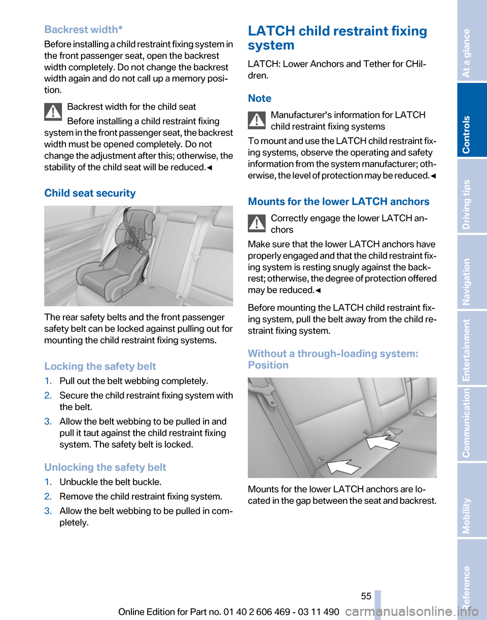
Child seat security The rear safety belts and the front passenger
safety belt can be locked against pulling out for
mounting the child restraint fixing systems.
Locking the safety belt
1.
Pull out the belt webbing completely.
2. Secure the child restraint fixing system with
the belt.
3. Allow the belt webbing to be pulled in and
pull it taut against the child restraint fixing
system. The safety belt is locked.
Unlocking the safety belt
1. Unbuckle the belt buckle.
2. Remove the child restraint fixing system.
3. Allow the belt webbing to be pulled in com‐
pletely. LATCH child restraint fixing
system
LATCH: Lower Anchors and Tether for CHil‐
dren.
Note
Manufacturer's information for LATCH
child restraint fixing systems
To
mount and use the LATCH child restraint fix‐
ing systems, observe the operating and safety
information from the system manufacturer; oth‐
erwise, the level of protection may be reduced.◀
Mounts for the lower LATCH anchors
Correctly engage the lower LATCH an‐
chors
Make sure that the lower LATCH anchors have
properly engaged and that the child restraint fix‐
ing system is resting snugly against the back‐
rest; otherwise, the degree of protection offered
may be reduced.◀
Before mounting the LATCH child restraint fix‐
ing system, pull the belt away from the child re‐
straint fixing system.
Without a through-loading system:
Position Mounts for the lower LATCH anchors are lo‐
cated
in the gap between the seat and backrest. Seite 55
55Online Edition for Part no. 01 40 2 606 469 - 03 11 490
Reference Mobility Communication Entertainment Navigation Driving tips
Controls At a glance
Page 87 of 304
Child restraint fixing system in the front
passenger seat
Before
transporting a child on the front passen‐
ger seat, see the safety notes and instructions
under Children on the front passenger seat.◀
Malfunction of the automatic
deactivation system
When transporting older children and adults, the
front passenger airbags may be deactivated in
certain sitting positions. In this case, the indica‐
tor lamp for the front passenger airbags lights
up.
In this case, change the sitting position so that
the front passenger airbags are activated and
the indicator lamp goes out.
If it is not possible to activate the airbags, have
the person sit in the rear.
To make sure that the occupied seat cushion
can be evaluated correctly
▷ Do not attach covers, cushions, ball mats or
other items to the front passenger seat un‐
less they are specifically recommended by
the manufacturer of your vehicle.
▷ Do not place any objects on the front pas‐
senger seat.
▷ Do not place objects under the seat that
could press against the seat from below.
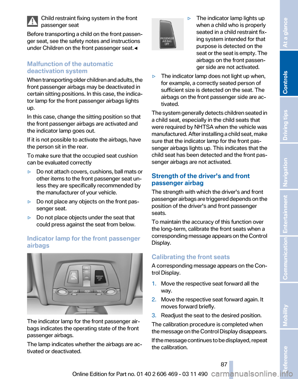
Indicator lamp for the front passenger
airbags The indicator lamp for the front passenger air‐
bags indicates the operating state of the front
passenger airbags.
The lamp indicates whether the airbags are ac‐
tivated or deactivated. ▷
The indicator lamp lights up
when a child who is properly
seated in a child restraint fix‐
ing system intended for that
purpose is detected on the
seat
or the seat is empty. The
airbags on the front passen‐
ger side are not activated.
▷ The indicator lamp does not light up when,
for example, a correctly seated person of
sufficient size is detected on the seat. The
airbags on the front passenger side are ac‐
tivated.
The system generally detects children seated in
a child seat, especially in the child seats that
were required by NHTSA when the vehicle was
manufactured.
After installing a child seat, make
sure that the indicator lamp for the front pas‐
senger airbags lights up. This indicates that the
child seat has been detected and the front pas‐
senger airbags are not activated.
Strength of the driver's and front
passenger airbag
The strength with which the driver's and front
passenger airbags are triggered depends on the
position of the driver's and front passenger
seats.
To maintain the accuracy of this function over
the long-term, calibrate the front seats when a
corresponding message appears on the Control
Display.
Calibrating the front seats
A corresponding message appears on the Con‐
trol Display.
1. Move the respective seat forward all the
way.
2. Move the respective seat forward again. It
moves forward briefly.
3. Readjust the seat to the desired position.
The calibration procedure is completed when
the
message on the Control Display disappears.
If the message continues to be displayed, repeat
the calibration. Seite 87
87Online Edition for Part no. 01 40 2 606 469 - 03 11 490
Reference Mobility Communication Entertainment Navigation Driving tips
Controls At a glance
Page 117 of 304

The display appears as soon as Top View is ac‐
tivated.
If
the backup camera image was selected last, it
again appears on the display. To switch to Top
View: "Rear view camera" Select the symbol on
the Control Display.
The
setting is stored for the remote control cur‐
rently in use.
Display on the Control Display
Switching on the backup camera via
iDrive
With Top View switched on: "Rear view camera"
The
backup camera image is displayed. The set‐
ting is stored for the remote control currently in
use.
Brightness
With Top View switched on:
1. "Brightness"
2. Turn the controller until the desired setting
is reached and press the controller.
Contrast
With Top View switched on:
1. "Contrast"
2. Turn the controller until the desired setting
is reached and press the controller. Displaying the turning circle and
pathway lines
▷
The static, red turning circle line shows the
space needed to the side of the vehicle
when the steering wheel is turned all the
way.
▷ The variable, green pathway line assists you
in assessing the amount of space actually
needed to the side of the vehicle.
The pathway line is dependent on the cur‐
rent steering angle and is continuously ad‐
justed with the steering wheel movement. "Parking aid lines"
Turning circle and pathway lines are displayed.
Cameras The objectives of the Top View cameras are lo‐
cated at the bottom of the exterior mirror hous‐
ings.
The image quality may be impaired by dirt.
Clean the lens, refer to page 276.
Side View*
The concept
Side View provides an early look at cross traffic
at blind driveways and intersections. Road users
concealed by obstacles to the left and right of
the vehicle can only be detected relatively late
from the driver's seat. To improve visibility, two
cameras in the front of the vehicle record the
traffic situation on each side.
System limits
The maximum recording range of the camera is
330 ft/100 m.
Seite 117
117Online Edition for Part no. 01 40 2 606 469 - 03 11 490
Reference Mobility Communication Entertainment Navigation Driving tips
Controls At a glance
Page 139 of 304
Close the glove compartment again im‐
mediately
Close
the glove compartment immediately after
use while driving; otherwise, injury may occur
during accidents.◀
Closing
Fold up the cover.
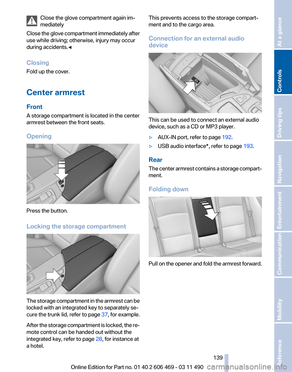
Center armrest
Front
A storage compartment is located in the center
armrest between the front seats.
Opening Press the button.
Locking the storage compartment
The storage compartment in the armrest can be
locked with an integrated key to separately se‐
cure
the trunk lid, refer to page 37, for example.
After the storage compartment is locked, the re‐
mote control can be handed out without the
integrated key, refer to page 28, for instance at
a hotel. This prevents access to the storage compart‐
ment and to the cargo area.
Connection for an external audio
device
This can be used to connect an external audio
device, such as a CD or MP3 player.
▷
AUX-IN port, refer to page 192.
▷ USB audio interface*, refer to page 193.
Rear
The
center armrest contains a storage compart‐
ment.
Folding down Pull on the opener and fold the armrest forward.
Seite 139
139Online Edition for Part no. 01 40 2 606 469 - 03 11 490
Reference Mobility Communication Entertainment Navigation Driving tips
Controls At a glance
Page 149 of 304
hicle and unstable driving situations may
result.
2. Determine the combined weight of the
driver and passengers that will be riding in
your vehicle.
3. Subtract the combined weight of the driver
and
passengers from XXX kilograms or YYY
pounds.
4. The resulting figure equals the available
amount
of cargo and luggage load capacity.
For example, if the YYY amount equals
1,000 lbs and there will be four 150 lbs pas‐
sengers in your vehicle, the amount of avail‐
able cargo and luggage load capacity is
400 lbs: 1,000 lbs minus 600 lbs = 400 lbs.
5. Determine the combined weight of luggage
and
cargo being loaded on the vehicle. That
weight may not safely exceed the available
cargo and luggage load capacity calculated
in Step 4.
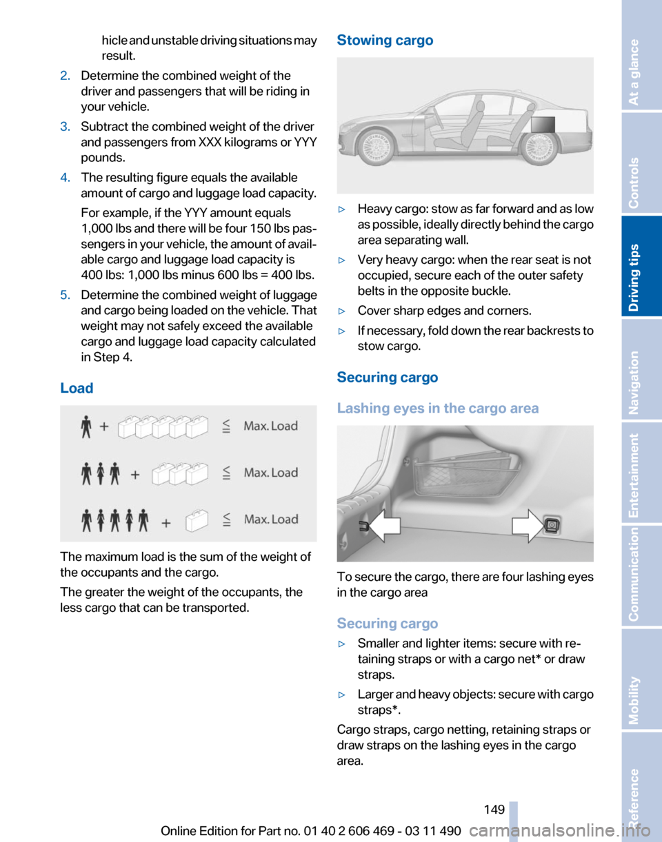
Load The maximum load is the sum of the weight of
the occupants and the cargo.
The greater the weight of the occupants, the
less cargo that can be transported. Stowing cargo ▷
Heavy cargo: stow as far forward and as low
as
possible, ideally directly behind the cargo
area separating wall.
▷ Very heavy cargo: when the rear seat is not
occupied, secure each of the outer safety
belts in the opposite buckle.
▷ Cover sharp edges and corners.
▷ If necessary, fold down the rear backrests to
stow cargo.
Securing cargo
Lashing eyes in the cargo area To secure the cargo, there are four lashing eyes
in the cargo area
Securing cargo
▷
Smaller and lighter items: secure with re‐
taining straps or with a
cargo net* or draw
straps.
▷ Larger and heavy objects: secure with cargo
straps*.
Cargo straps, cargo netting, retaining straps or
draw straps on the lashing eyes in the cargo
area.
Seite 149
149Online Edition for Part no. 01 40 2 606 469 - 03 11 490
Reference Mobility Communication Entertainment Navigation
Driving tips Controls At a glance