2011 BMW 528I navigation system
[x] Cancel search: navigation systemPage 43 of 304

Initializing after a power failure
After
a power failure during the opening or clos‐
ing process, the roof can only be operated to a
limited extent.
Initializing the system
The system can be initialized when the vehicle
is stationary and the engine is running.
Danger of pinching
Monitor the closing process and make
sure that the closing path of the glass sunroof is
clear; otherwise, injuries may result.◀
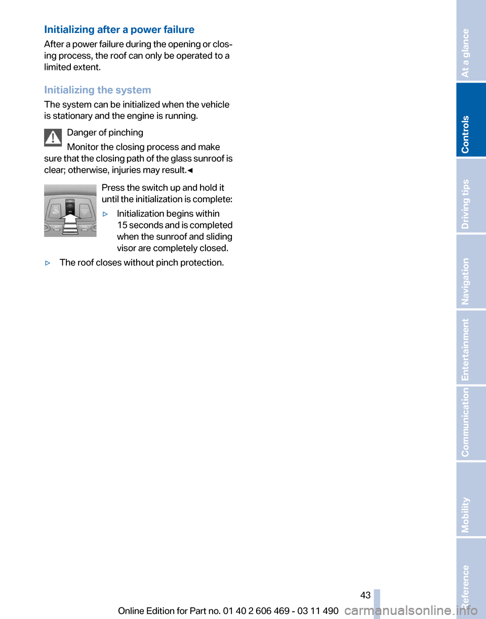
Press the switch up and hold it
until the initialization is complete:
▷Initialization begins within
15
seconds and is completed
when the sunroof and sliding
visor are completely closed.
▷ The roof closes without pinch protection. Seite 43
43Online Edition for Part no. 01 40 2 606 469 - 03 11 490
Reference Mobility Communication Entertainment Navigation Driving tips
Controls At a glance
Page 55 of 304

Backrest width*
Before
installing a child restraint fixing system in
the front passenger seat, open the backrest
width completely. Do not change the backrest
width again and do not call up a memory posi‐
tion.
Backrest width for the child seat
Before installing a child restraint fixing
system in the front passenger seat, the backrest
width must be opened completely. Do not
change the adjustment after this; otherwise, the
stability of the child seat will be reduced.◀
Child seat security The rear safety belts and the front passenger
safety belt can be locked against pulling out for
mounting the child restraint fixing systems.
Locking the safety belt
1.
Pull out the belt webbing completely.
2. Secure the child restraint fixing system with
the belt.
3. Allow the belt webbing to be pulled in and
pull it taut against the child restraint fixing
system. The safety belt is locked.
Unlocking the safety belt
1. Unbuckle the belt buckle.
2. Remove the child restraint fixing system.
3. Allow the belt webbing to be pulled in com‐
pletely. LATCH child restraint fixing
system
LATCH: Lower Anchors and Tether for CHil‐
dren.
Note
Manufacturer's information for LATCH
child restraint fixing systems
To
mount and use the LATCH child restraint fix‐
ing systems, observe the operating and safety
information from the system manufacturer; oth‐
erwise, the level of protection may be reduced.◀
Mounts for the lower LATCH anchors
Correctly engage the lower LATCH an‐
chors
Make sure that the lower LATCH anchors have
properly engaged and that the child restraint fix‐
ing system is resting snugly against the back‐
rest; otherwise, the degree of protection offered
may be reduced.◀
Before mounting the LATCH child restraint fix‐
ing system, pull the belt away from the child re‐
straint fixing system.
Without a through-loading system:
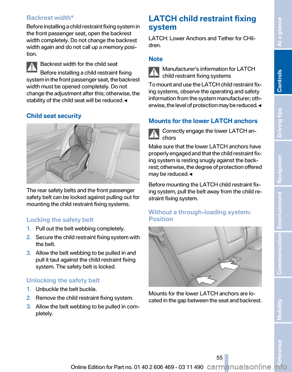
Position Mounts for the lower LATCH anchors are lo‐
cated
in the gap between the seat and backrest. Seite 55
55Online Edition for Part no. 01 40 2 606 469 - 03 11 490
Reference Mobility Communication Entertainment Navigation Driving tips
Controls At a glance
Page 63 of 304

Switching off and brief wipe
Press the wiper levers down.
The lever automatically returns to its initial po‐
sition when released.
▷
Brief wipe: press down once.
▷ To switch off normal wipe: press down once.
▷ To switch off fast wipe: press down twice.
Rain sensor
The concept
The time between wipes is controlled automat‐
ically
and depends on the intensity of the rainfall.
The sensor is located on the windshield, directly
in front of the interior rearview mirror.
Activating/deactivating the rain sensor Press the button on the wiper lever.
When
activated, the wipers move over the wind‐
shield once.
The LED in the steering column stalk lights up. Deactivate the rain sensor in car washes
Deactivate the rain sensor when passing
through
an automatic car wash; otherwise, dam‐
age could be caused by undesired wiper activa‐
tion.◀
Rain sensor sensitivity Turn the thumbwheel.
Clean the windshield,
headlamps* Pull the lever.
The system sprays washer fluid on the wind‐
shield and activates the wipers briefly.
In
addition, the headlamps are cleaned at regular
intervals when the vehicle lights are switched
on.
Do not use the washer system at freezing
temperatures
Do not use the washers if there is any danger
that the fluid will freeze on the windshield; oth‐
erwise, your vision could be obscured. For this
reason, use antifreeze.
Avoid using the washer when the reservoir is
empty; otherwise, you could damage the
pump.◀ Seite 63
63Online Edition for Part no. 01 40 2 606 469 - 03 11 490
Reference Mobility Communication Entertainment Navigation Driving tips
Controls At a glance
Page 70 of 304

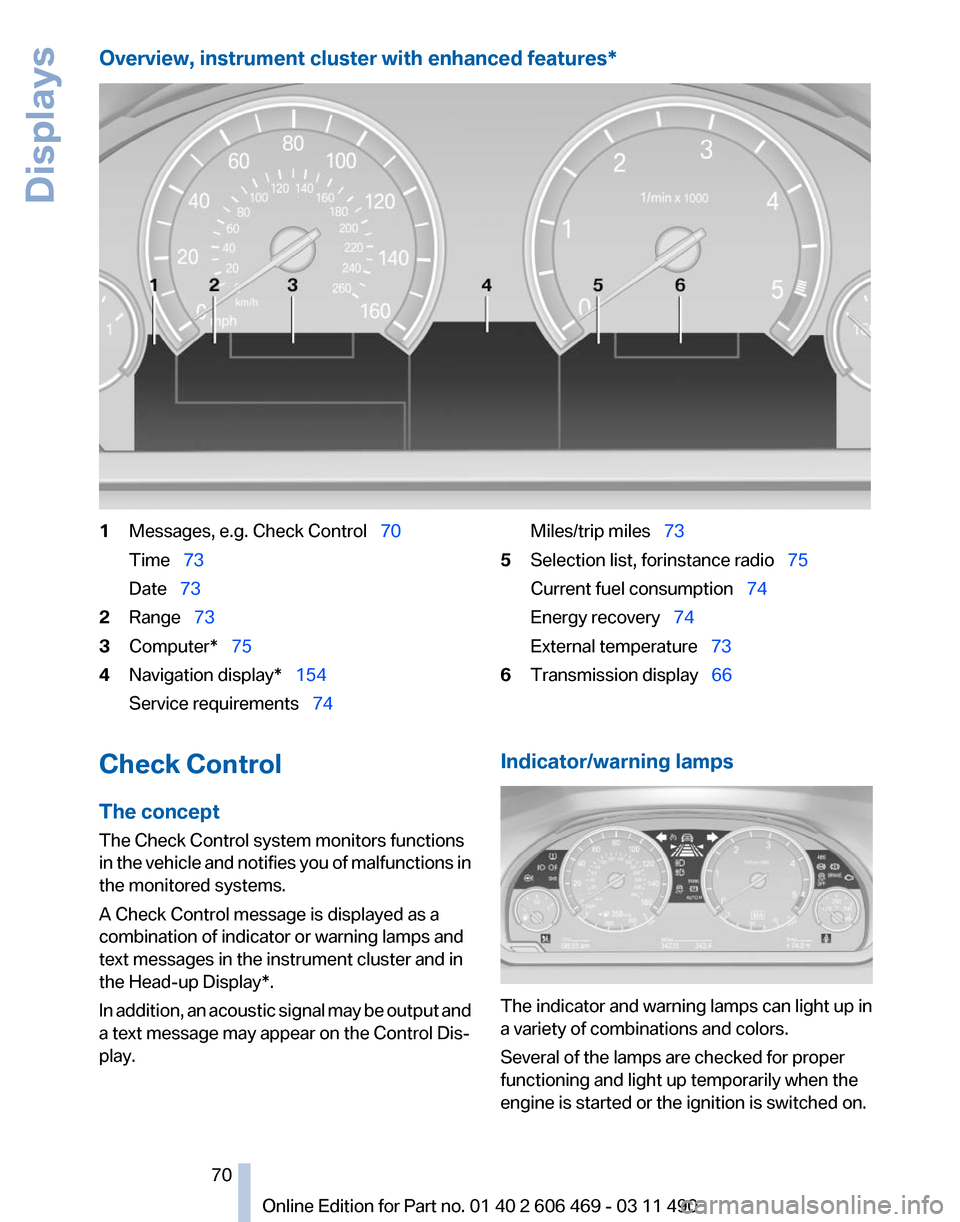
Overview, instrument cluster with enhanced features*
1
Messages, e.g. Check Control 70
Time 73
Date 73
2 Range 73
3 Computer* 75
4 Navigation display* 154
Service requirements 74 Miles/trip miles
73
5 Selection list, for instance radio 75
Current fuel consumption 74
Energy recovery 74
External temperature 73
6 Transmission display 66
Check Control
The concept
The Check Control system monitors functions
in
the vehicle and notifies you of malfunctions in
the monitored systems.
A Check Control message is displayed as a
combination of indicator or warning lamps and
text messages in the instrument cluster and in
the Head-up Display*.
In addition, an acoustic signal may be output and
a text message may appear on the Control Dis‐
play. Indicator/warning lamps
The indicator and warning lamps can light up in
a variety of combinations and colors.
Several of the lamps are checked for proper
functioning and light up temporarily when the
engine is started or the ignition is switched on.
Seite 70
70 Online Edition for Part no. 01 40 2 606 469 - 03 11 490
Displays
Page 71 of 304

Overview: indicator/warning lamps
Symbol Function or system
Turn signal
Parking brake
Parking brake in Canadian models
Automatic Hold*
Front fog lamps*
High beams
High-beam Assistant*
Parking lamps, headlamp control
Active Cruise Control*
Vehicle detection, Active Cruise
Control*
Cruise control*
Lane departure warning*
DSC Dynamic Stability Control
DSC Dynamic Stability Control or
DTC Dynamic Traction Control
Tire Pressure Monitor* Symbol Function or system
Safety belts
Airbag system
Steering system
Emissions
Brake system
Brake system in Canadian models
Antilock Brake System ABS
Antilock Brake System ABS in Cana‐
dian models
Text messages
Text
messages in combination with a symbol in
the instrument cluster explain a Check Control
message and the meaning of the indicator and
warning lamps.
Supplementary text messages
Addition information, such as on the cause of a
fault or the required action, can be called up via
Check Control. The supplementary text of ur‐
gent messages is displayed automatically.
It is shown on the Control Display.
Symbols
Depending on the Check Control message, the
following functions can be selected.
▷ "Owner's Manual"
Display additional information about the
Check Control message in the integrated
owner's manual.
Seite 71
71Online Edition for Part no. 01 40 2 606 469 - 03 11 490
Reference Mobility Communication Entertainment Navigation Driving tips
Controls At a glance
Page 75 of 304

6.
Create the settings.
7. Confirm.
The entered date is stored.
Automatic Service Request*
Data regarding the maintenance status or legally
mandated inspections of the vehicle are auto‐
matically transmitted to your service center be‐
fore a service due date.
You can check when your service center was
notified.
1. "Vehicle Info"
2. "Vehicle status"
3. Open "Options".
4. "Last Service Request"
Gear shift indicator*
The concept
The
system recommends the most fuel efficient
gear in the current driving situation.
Indicators to shift up or down are displayed in
the instrument cluster.
Displays 1
Fuel efficient gear is engaged
2 Shift up to fuel efficient gear
3 Shift down to fuel efficient gear Selection lists in the
instrument cluster
The concept
The following can be operated using the buttons
and the thumbwheel on the steering wheel:
▷
Current audio source.
▷ Redial on telephone*.
▷ Activation of the voice activation system*.
Activating a list and creating the
setting Press a button on the right side of the steering
wheel
or turn the thumbwheel to activate the re‐
quired list.
Create the setting using the thumbwheel.
Computer
Indication in the info display
The information from the com‐
puter is shown in the Info display
in the instrument cluster. Seite 75
75Online Edition for Part no. 01 40 2 606 469 - 03 11 490
Reference Mobility Communication Entertainment Navigation Driving tips
Controls At a glance
Page 76 of 304

Calling up information on the info
display
Press the computer button on the turn signal
lever.
Information
is displayed on the info display of the
instrument cluster.
Information at a glance
Repeatedly pressing the button on the turn sig‐
nal lever calls up the following information on the
info display:
▷ Range.
▷ Average fuel consumption.
▷ Average speed.
▷ Date*.
▷ Time of arrival*
When destination guidance is activated in
the navigation system.
▷ Distance to destination*
When destination guidance is activated in
the navigation system.
▷ Arrow view of navigation system*
When destination guidance is activated in
the navigation system.
Adjusting the info display
You can select what information from the com‐
puter
is to be displayed on the info display of the
instrument cluster.
1. "Settings"
2. "Info display" 3.
Select the desired displays. Information in detail
Range
Displays the estimated cruising range available
with the remaining fuel.
It is calculated based on your driving style over
the last 20 miles/30 km.
If there is only enough fuel left for less than
45
miles/80 km, the color of the display changes.
Average fuel consumption
This is calculated for the period during which the
engine is running.
The average fuel consumption is calculated on
the basis of various distances.
Average speed
Periods in which the vehicle is parked with the
engine stopped do not enter into the calculation.
Resetting average values
Press and hold the computer button on the turn
signal lever.
Distance to destination*
The distance remaining to the destination is dis‐
played if a destination is entered in the naviga‐
tion system* before the trip is started.
The distance to the destination is adopted au‐
tomatically.
Seite 76
76 Online Edition for Part no. 01 40 2 606 469 - 03 11 490
Displays
Page 77 of 304

Time of arrival*
The estimated time of arrival is
displayed if a destination is en‐
tered in the navigation system
*
before the trip is started.
The time must be correctly set.
Speed limit
Display of a speed limit which, when reached,
should cause a warning to be issued.
Renewed warning if the vehicle speed drops be‐
low the set speed limit once by at least 3 mph/
5 km/h.
Displaying, setting or changing the
limit
1. "Settings"
2. "Speed"
3. "Warning at:" 4.
Turn the controller until the desired limit is
displayed.
5. Press the controller.
The speed limit is stored.
Activating/deactivating the limit
1. "Settings"
2. "Speed"
3. "Warning"
4. Press the controller.
Applying your current speed as the
limit
1. "Settings"
2. "Speed" 3.
"Select current speed"
4. Press the controller.
The current vehicle speed is stored as the
limit.
Resetting values
The average fuel consumption and average
speed can be reset.
Press
and hold the computer button on the turn
signal lever.
Trip computer
There are two types of computer.
▷ "Onboard info": the values can be reset as
often as necessary.
▷ "Trip
computer": the values provide an over‐
view of the current trip.
Resetting the trip computer
1. "Vehicle Info"
2. "Trip computer"
3. "Reset": all values are reset.
"Automatically reset": all values are reset
approx.
4 hours after the vehicle comes to a
standstill. Display on the Control Display
Display the computer or trip computer on the
Control Display.
1.
"Vehicle Info"
2. "Onboard info" or "Trip computer"
Seite 77
77Online Edition for Part no. 01 40 2 606 469 - 03 11 490
Reference Mobility Communication Entertainment Navigation Driving tips
Controls At a glance