Page 132 of 230
4-51
ENGINE REMOVAL
2. Install:
• Lock washer "1"
• Nut (drive sprocket) "2"
Tighten the nut while applying the
rear brake.
Make sure to tighten to specifica-
tion; otherwise, it may damage the
other part that is fastened togeth-
er.
3. Bend the lock washer tab to lock
the nut.
4. Install:
• Drive chain sprocket guide
• Drive chain sprocket cover "1"
• Bolt(drive chain sprocket cover)
"2"Nut (drive sprocket):
75 Nm (7.5 m•kg, 54
ft•lb)
Bolt (drive chain sprock-
et cover):
7 Nm (0.7 m•kg, 5.1
ft•lb)
Page 133 of 230
4-52
CRANKCASE AND CRANKSHAFT
CRANKCASE AND CRANKSHAFT
REMOVING THE CRANKSHAFT
Order Part name Q'ty Remarks
Engine Refer to "ENGINE REMOVAL" section.
Piston Refer to "CYLINDER AND PISTON" section.
Balancer Refer to "BALANCER" section.
Kick shaft assemblyRefer to "KICK SHAFT AND SHIFT SHAFT"
section.
SegmentRefer to "KICK SHAFT AND SHIFT SHAFT"
section.
Stator Refer to "AC MAGNETO" section.
1 Timing chain guide (exhaust side) 1
2 Timing chain guide stopper plate 1
3 Timing chain 1
4 Bolt [L = 50 mm (1.97 in)] 7 Refer to removal section.
5 Bolt [L = 60 mm (2.36 in)] 2 Refer to removal section.
6 Bolt [L = 70 mm (2.76 in)] 4 Refer to removal section.
7 Right crankcase 1 Refer to removal section.
8 Left crankcase 1 Refer to removal section.
9 Oil strainer 1
Page 136 of 230

4-55
CRANKCASE AND CRANKSHAFT
DISASSEMBLING THE
CRANKCASE
1. Separate:
• Right crankcase
• Left crankcase
Separation steps:
a. Remove the crankcase bolts,
hose guide and clutch cable hold-
er.
Loosen each bolt 1/4 of a turn at a
time and after all the bolts are loos-
ened, remove them.
b. Remove the right crankcase "1".
• Place the crankcase with its left
side downward and split it by insert-
ing a screwdriver tip into the split-
ting slit "a" in the crankcase.
• Lift the right crankcase horizontally
while lightly patting the case split-
ting slit and engine mounting boss
using a soft hammer, and leave the
crankshaft and transmission with
the left crankcase.
Use soft hammer to tap on the
case half. Tap only on reinforced
portions of case. Do not tap on
gasket mating surface. Work slow-
ly and carefully. Make sure the
case halves separate evenly. If the
cases do not separate, check for a
remaining case bolt or fitting. Do
not force.
c. Remove the dowel pins and O-
ring.
REMOVING THE BALANCER
SHAFT
1. Remove:
• Balancer shaft "1"
Remove the balancer shaft with its
flat side "a" facing the crankshaft.
REMOVING THE CRANKSHAFT
1. Remove:
• Crankshaft "1"
Use the crankcase separating
tool "2".
• Install the crankcase separating
tool as shown.
• Do not use a hammer to drive out
the crankshaft.
REMOVING THE CRANKCASE
BEARING
1. Remove:
• Bearing "1"
• Remove the bearing from the
crankcase by pressing its inner
race.
• Do not use the removed bearing.
CHECKING THE TIMING CHAIN
AND TIMING CHAIN GUIDE
1. Inspect:
• Timing chain
Cracks/stiff→Replace the timing
chain and camshaft sprocket as a
set.
2. Inspect:
• Timing chain guide
Wear/damage→Replace.
CHECKING THE CRANKCASE
1. Inspect:
• Contacting surface "a"
Scratches → Replace.
• Engine mounting boss "b", crank-
case
Cracks/damage → Replace.
2. Inspect:
• Bearing
Rotate inner race with a finger.
Rough spot/seizure → Replace.
Crankcase separating
tool:
YU-A9642/90890-04152
Page 138 of 230

4-57
CRANKCASE AND CRANKSHAFT
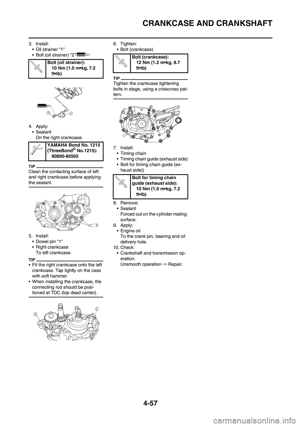
3. Install:
• Oil strainer "1"
• Bolt (oil strainer) "2"
4. Apply:
• Sealant
On the right crankcase.
Clean the contacting surface of left
and right crankcase before applying
the sealant.
5. Install:
• Dowel pin "1"
• Right crankcase
To left crankcase.
• Fit the right crankcase onto the left
crankcase. Tap lightly on the case
with soft hammer.
• When installing the crankcase, the
connecting rod should be posi-
tioned at TDC (top dead center).
6. Tighten:
• Bolt (crankcase)
Tighten the crankcase tightening
bolts in stage, using a crisscross pat-
tern.
7. Install:
• Timing chain
• Timing chain guide (exhaust side)
• Bolt for timing chain guide (ex-
haust side))
8. Remove:
• Sealant
Forced out on the cylinder mating
surface.
9. Apply:
• Engine oil
To the crank pin, bearing and oil
delivery hole.
10. Check:
• Crankshaft and transmission op-
eration.
Unsmooth operation→Repair. Bolt (oil strainer):
10 Nm (1.0 m•kg, 7.2
ft•lb)
YAMAHA Bond No. 1215
(ThreeBond® No.1215):
90890-85505
Bolt (crankcase):
12 Nm (1.2 m•kg, 8.7
ft•lb)
Bolt for timing chain
guide (exhaust side):
10 Nm (1.0 m•kg, 7.2
ft•lb)
Page 139 of 230
4-58
TRANSMISSION, SHIFT CAM AND SHIFT FORK
TRANSMISSION, SHIFT CAM AND SHIFT FORK
REMOVING THE TRANSMISSION, SHIFT CAM AND SHIFT FORK
Order Part name Q'ty Remarks
Engine Refer to "ENGINE REMOVAL" section.
Separate the crankcase.Refer to "CRANKCASE AND CRANK-
SHAFT" section.
1 Main axle 1 Refer to removal section.
2 Drive axle 1 Refer to removal section.
3 Shift cam 1 Refer to removal section.
4 Shift fork 3 1 Refer to removal section.
5 Shift fork 2 1 Refer to removal section.
6 Shift fork 1 1 Refer to removal section.
7 Collar 1
Page 141 of 230

4-60
TRANSMISSION, SHIFT CAM AND SHIFT FORK
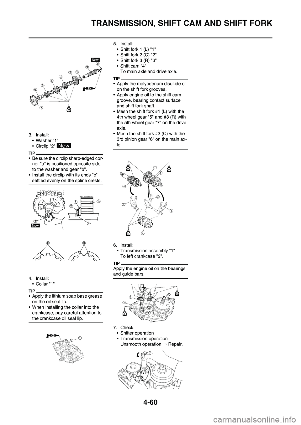
3. Install:
• Washer "1"
• Circlip "2"
• Be sure the circlip sharp-edged cor-
ner "a" is positioned opposite side
to the washer and gear "b".
• Install the circlip with its ends "c"
settled evenly on the spline crests.
4. Install:
•Collar "1"
• Apply the lithium soap base grease
on the oil seal lip.
• When installing the collar into the
crankcase, pay careful attention to
the crankcase oil seal lip.
5. Install:
• Shift fork 1 (L) "1"
• Shift fork 2 (C) "2"
• Shift fork 3 (R) "3"
• Shift cam "4"
To main axle and drive axle.
• Apply the molybdenum disulfide oil
on the shift fork grooves.
• Apply engine oil to the shift cam
groove, bearing contact surface
and shift fork shaft.
• Mesh the shift fork #1 (L) with the
4th wheel gear "5" and #3 (R) with
the 5th wheel gear "7" on the drive
axle.
• Mesh the shift fork #2 (C) with the
3rd pinion gear "6" on the main ax-
le.
6. Install:
• Transmission assembly "1"
To left crankcase "2".
Apply the engine oil on the bearings
and guide bars.
7. Check:
• Shifter operation
• Transmission operation
Unsmooth operation→Repair.
Page 142 of 230
5-1
FRONT WHEEL AND REAR WHEEL
CHASSIS
This section is intended for those who have basic knowledge and skill concerning the servicing of Yamaha motorcycles
(e.g., Yamaha dealers, service engineers, etc.) Those who have little knowledge and skill concerning servicing are request-
ed not to undertake inspection, adjustment, disassembly, or reassembly only by reference to this manual. It may lead to
servicing trouble and mechanical damage.
FRONT WHEEL AND REAR WHEEL
REMOVING THE FRONT WHEEL
Order Part name Q'ty Remarks Hold the machine by placing the suitable stand
under the engine. Refer to "HANDLING NOTE".
1 Bolt (axle holder) 4 Only loosening.
2 Nut (front wheel axle) 1
3 Front wheel axle 1
4 Front wheel 1
5 Collar 2
6 Oil seal 2
7 Bearing 2 Refer to removal section.
8 Brake disc 1
Page 143 of 230
5-2
FRONT WHEEL AND REAR WHEEL
REMOVING THE REAR WHEEL
Order Part name Q'ty Remarks
Hold the machine by placing the suitable stand
under the engine.Refer to "HANDLING NOTE".
1 Nut (rear wheel axle) 1
2 Rear wheel axle 1
3 Drive chain puller 2
4 Rear wheel 1 Refer to removal section.
5 Collar 2
6 Rear wheel sprocket 1
7 Oil seal 2
8 Circlip 1
9 Bearing 3 Refer to removal section.
10 Brake disc 1
5