Page 6 of 82

TABLE OF CONTENTSSAFETY INFORMATION ..................1-1
Further safe-riding points ................1-5
DESCRIPTION ..................................2-1
Left view ..........................................2-1
Right view ........................................2-3
Controls and instruments.................2-5
INSTRUMENT AND CONTROL
FUNCTIONS.......................................3-1
Main switch/steering lock ................3-1
Indicator and warning lights ............3-1
Speedometer ..................................3-2
Fuel gauge ......................................3-2
Coolant temperature gauge ............3-3
Multi-function display ......................3-3
Handlebar switches ........................3-6
Front brake lever ............................3-7
Rear brake lever .............................3-7
Fuel tank cap ..................................3-7
Fuel .................................................3-8
Catalytic converters ........................3-9
Seat ..............................................3-10
Storage compartments .................3-11
Windshield ....................................3-12
Adjusting the shock absorber
assemblies ................................3-13
Carrier (if applicable) ....................3-13
Luggage hook ...............................3-14
Sidestand ......................................3-14
Ignition circuit cut-off system ........3-15FOR YOUR SAFETY –
PRE-OPERATION CHECKS............. 4-1
OPERATION AND IMPORTANT
RIDING POINTS................................. 5-1
Starting the engine ......................... 5-1
Starting off ...................................... 5-2
Acceleration and deceleration ........ 5-2
Braking ........................................... 5-3
Tips for reducing fuel
consumption ............................... 5-3
Engine break-in .............................. 5-4
Parking ........................................... 5-4
PERIODIC MAINTENANCE AND
ADJUSTMENT................................... 6-1
Owner’s tool kit ............................... 6-1
Periodic maintenance chart for the
emission control system ............. 6-2
General maintenance and
lubrication chart .......................... 6-3
Removing and installing cowlings
and panels .................................. 6-6
Checking the spark plug ................. 6-7
Engine oil ....................................... 6-8
Final transmission oil .................... 6-10
Coolant ......................................... 6-11
Air filter and V-belt case air filter
elements ................................... 6-12
Checking the throttle cable free
play ........................................... 6-13Valve clearance ........................... 6-14
Tires ............................................. 6-14
Cast wheels ................................. 6-16
Front and rear brake lever free
play ........................................... 6-16
Checking the front and rear brake
pads .......................................... 6-17
Checking the brake fluid level ...... 6-17
Changing the brake fluid .............. 6-18
Checking and lubricating the
cables ....................................... 6-19
Checking and lubricating the
throttle grip and cable ............... 6-19
Lubricating the front and rear
brake levers .............................. 6-19
Checking and lubricating the
centerstand and sidestand ....... 6-20
Checking the front fork ................. 6-20
Checking the steering .................. 6-21
Checking the wheel bearings ....... 6-21
Battery ......................................... 6-22
Replacing the fuses ..................... 6-23
Replacing a headlight bulb .......... 6-24
Replacing a front turn signal light
bulb ........................................... 6-26
Replacing a tail/brake light bulb
or a rear turn signal light bulb ... 6-26
Replacing the license plate light
bulb ........................................... 6-27
Replacing an auxiliary light
bulb ........................................... 6-27U5B2E2E0.book Page 1 Friday, July 3, 2009 7:54 PM
Page 12 of 82

SAFETY INFORMATION
1-5
1
EAU10372
Further safe-riding points �
Be sure to signal clearly when
making turns.
�
Braking can be extremely difficult
on a wet road. Avoid hard braking,
because the scooter could slide.
Apply the brakes slowly when
stopping on a wet surface.
�
Slow down as you approach a cor-
ner or turn. Once you have com-
pleted a turn, accelerate slowly.
�
Be careful when passing parked
cars. A driver might not see you
and open a door in your path.
�
Railroad crossings, streetcar rails,
iron plates on road construction
sites, and manhole covers be-
come extremely slippery when
wet. Slow down and cross them
with caution. Keep the scooter up-
right, otherwise it could slide out
from under you.
�
The brake pads could get wet
when you wash the scooter. After
washing the scooter, check the
brakes before riding.
�
Always wear a helmet, gloves,
trousers (tapered around the cuff
and ankle so they do not flap), and
a bright colored jacket.
�
Do not carry too much luggage on
the scooter. An overloaded scoot-
er is unstable. Use a strong cord to
secure any luggage to the carrier
(if equipped). A loose load will af-
fect the stability of the scooter and
could divert your attention from the
road. (See page 1-1.)
U5B2E2E0.book Page 5 Friday, July 3, 2009 7:54 PM
Page 13 of 82
DESCRIPTION
2-1
2
EAU32220
Left viewWithout rear carrier
1
2 3 4 5 76 8
1. Rear storage compartment (page 3-11)
2. Shock absorber assembly spring preload adjusting ring (page 3-13)
3. Final transmission oil filler cap (page 6-10)
4. Air filter element (page 6-12)
5. V-belt case air filter element (page 6-12)
6. Sidestand (page 3-14)
7. Coolant level check window (page 6-11)8. Front brake pads (page 6-17)
U5B2E2E0.book Page 1 Friday, July 3, 2009 7:54 PM
Page 14 of 82
DESCRIPTION
2-2
2With rear carrier
1
2 3 4 5 76 8
1. Rear storage compartment (page 3-11)
2. Shock absorber assembly spring preload adjusting ring (page 3-13)
3. Final transmission oil filler cap (page 6-10)
4. Air filter element (page 6-12)
5. V-belt case air filter element (page 6-12)
6. Sidestand (page 3-14)
7. Coolant level check window (page 6-11)
8. Front brake pads (page 6-17)U5B2E2E0.book Page 2 Friday, July 3, 2009 7:54 PM
Page 15 of 82
DESCRIPTION
2-3
2
EAU32230
Right viewWithout rear carrier
2 13 4
5 6 7 8
1. Grab bar (page 5-2)
2. Main fuse/fuse box (page 6-23)
3. Battery (page 6-22)
4. Coolant reservoir cap (page 6-11)
5. Fuel tank cap (page 3-7)
6. Engine oil filler cap (page 6-8)
7. Centerstand (page 6-20)8. Rear brake pads (page 6-17)
U5B2E2E0.book Page 3 Friday, July 3, 2009 7:54 PM
Page 16 of 82
DESCRIPTION
2-4
2With rear carrier
2 13 4
5 6 7 8
1. Grab bar (page 5-2)
2. Main fuse/fuse box (page 6-23)
3. Battery (page 6-22)
4. Coolant reservoir cap (page 6-11)
5. Fuel tank cap (page 3-7)
6. Engine oil filler cap (page 6-8)
7. Centerstand (page 6-20)
8. Rear brake pads (page6-17)U5B2E2E0.book Page 4 Friday, July 3, 2009 7:54 PM
Page 17 of 82
DESCRIPTION
2-5
2
EAU10430
Controls and instruments
PUSHOPEN
12 3456 789
1. Rear brake lever (page 3-7)
2. Left handlebar switches (page 3-6)
3. Front storage compartment (page 3-11)
4. Speedometer/Multi-function display (page 3-2/page 3-3)
5. Luggage hook (page 3-14)
6. Main switch/steering lock (page 3-1)
7. Right handlebar switch (page 3-6)
8. Throttle grip (page 6-13)9. Front brake lever (page 3-7)
U5B2E2E0.book Page 5 Friday, July 3, 2009 7:54 PM
Page 23 of 82

INSTRUMENT AND CONTROL FUNCTIONS
3-6
3
TIP�
The oil change indicator will come
on at the initial 1000 km (600 mi)
and every 3000 km (1800 mi)
thereafter.
�
If the engine oil is changed before
the oil change indicator comes on
(i.e. before the periodic oil change
interval has been reached), the in-
dicator must be reset after the oil
change for the next periodic oil
change to be indicated at the cor-
rect time. After resetting, the indi-
cator will come on for two seconds.
If the indicator does not come on,
repeat the procedure.
EAU12348
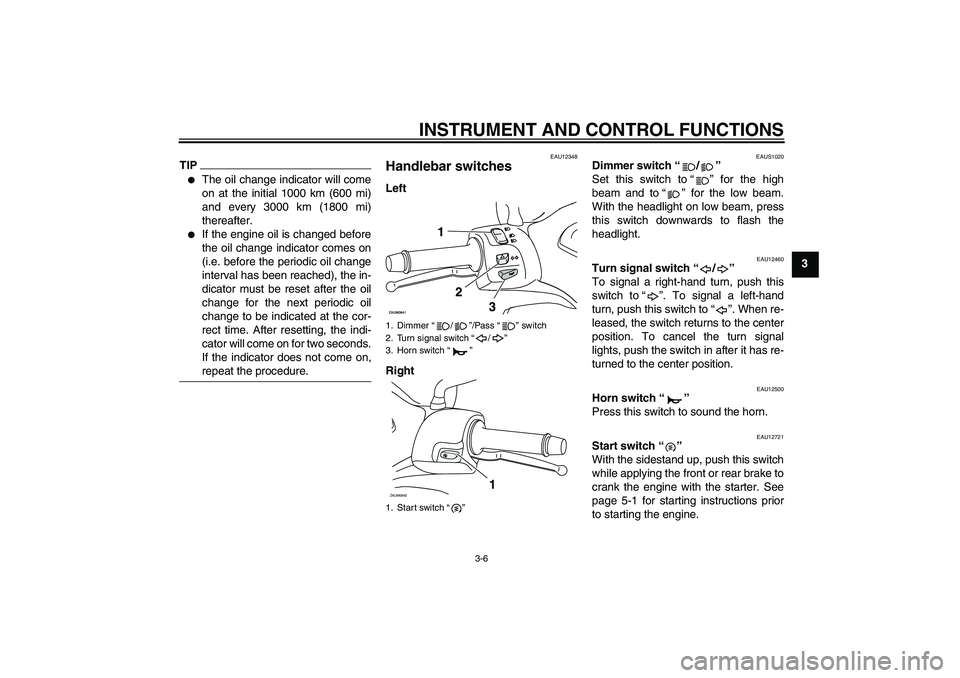
Handlebar switches Left
Right
EAUS1020
Dimmer switch“/”
Set this switch to“” for the high
beam and to“” for the low beam.
With the headlight on low beam, press
this switch downwards to flash the
headlight.
EAU12460
Turn signal switch“/”
To signal a right-hand turn, push this
switch to“”. To signal a left-hand
turn, push this switch to“”. When re-
leased, the switch returns to the center
position. To cancel the turn signal
lights, push the switch in after it has re-
turned to the center position.
EAU12500
Horn switch“”
Press this switch to sound the horn.
EAU12721
Start switch“”
With the sidestand up, push this switch
while applying the front or rear brake to
crank the engine with the starter. See
page 5-1 for starting instructions prior
to starting the engine.
1. Dimmer“/”/Pass“” switch
2. Turn signal switch“/”
3. Horn switch“”
1. Start switch“”ZAUM0642
1
U5B2E2E0.book Page 6 Friday, July 3, 2009 7:54 PM