Page 214 of 230

7-6
ELECTRIC STARTING SYSTEM
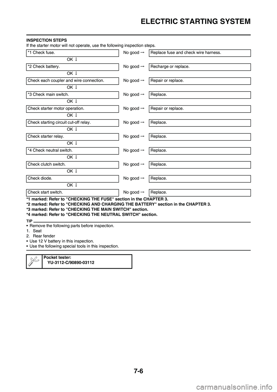
INSPECTION STEPS
If the starter motor will not operate, use the following inspection steps.
*1 marked: Refer to "CHECKING THE FUSE" section in the CHAPTER 3.
*2 marked: Refer to "CHECKING AND CHARGING THE BATTERY" section in the CHAPTER 3.
*3 marked: Refer to "CHECKING THE MAIN SWITCH" section.
*4 marked: Refer to "CHECKING THE NEUTRAL SWITCH" section.
• Remove the following parts before inspection.
1. Seat
2. Rear fender
• Use 12 V battery in this inspection.
• Use the following special tools in this inspection.
*1 Check fuse. No good→Replace fuse and check wire harness.
OK↓
*2 Check battery. No good→Recharge or replace.
OK↓
Check each coupler and wire connection. No good→Repair or replace.
OK↓
*3 Check main switch. No good→Replace.
OK↓
Check starter motor operation. No good→Repair or replace.
OK↓
Check starting circuit cut-off relay. No good→Replace.
OK↓
Check starter relay. No good→Replace.
OK↓
*4 Check neutral switch. No good→Replace.
OK↓
Check clutch switch. No good→Replace.
OK↓
Check diode. No good→Replace.
OK↓
Check start switch. No good→Replace.
Pocket tester:
YU-3112-C/90890-03112
Page 221 of 230
7-13
CHARGING SYSTEM
CHARGING SYSTEM
INSPECTION STEPS
If the battery is not charged, use the following inspection steps.
*1 marked: Refer to "CHECKING THE FUSE" section in the CHAPTER 3.
*2 marked: Refer to "CHECKING AND CHARGING THE BATTERY" section in the CHAPTER 3.
• Remove the following parts before inspection.
1. Seat
2. Fuel tank
• Use the following special tools in this inspection.
*1 Check fuse. No good→Replace fuse and check wire harness.
OK↓
*2 Check battery. No good→Recharge or replace.
OK↓
Check each coupler and wire connection. No good→Repair or replace.
OK↓
Check charging voltage. OK→Charging system is good.
No good↓
Check AC magneto. (Charging coil) No good→Replace.
OK↓
Replace rectifier/regulator.
Pocket tester:
YU-3112-C/90890-03112
Page 222 of 230
7-14
CHARGING SYSTEM
CHECKING THE COUPLERS AND
LEADS CONNECTION
1. Check:
• Couplers and leads connection
Rust/dust/looseness/short-circuit
→Repair or replace.
CHECKING THE CHARGING
VOLTAGE
1. Start the engine.
2. Inspect:
• Charging voltage
Out of specification→If no failure
is found in checking the source
coil resistance, replace the rectifi-
er/regulator.
3. Inspect:
• Charging coil resistance
Out of specification→Replace. Tester (+) lead→Red lead "1"
Tester (-) lead→Black lead "2"
Charging
voltageTester se-
lector posi-
tion
14.0–15.0 V
at 5,000 r/
minDCV-20
Tester (+) lead→White lead "1"
Tester (-) lead→Ground "2"
Charging
coil resis-
tanceTester se-
lector posi-
tion
0.288–0.432
Ω at 20 °C
(68 °F)Ω × 1
Page 228 of 230
7-20
SIGNALING SYSTEM
SIGNALING SYSTEM
INSPECTION STEPS
If the speedometer will not operate, use the following inspection steps.
*1 marked: Refer to "CHECKING AND CHARGING THE BATTERY" section in the CHAPTER 3.
• Remove the following parts before inspection.
1. Headlight
• Use the following special tools in this inspection.
*1 Check battery. No good→Recharge or replace.
OK↓
Check each coupler and wire connection. No good→Repair or replace.
OK↓
Check multi-function display. (Input voltage) No good→Replace wire harness.
OK↓
Check multi-function display. (Output voltage) No good→Replace multi-function display.
OK↓
Check speed sensor. No good→Replace.
Pocket tester:
YU-3112-C/90890-03112