Page 37 of 102

INSTRUMENT AND CONTROL FUNCTIONS
3-23
3
Compression damping force
The compression damping force is ad-
justed on the left front fork leg only. To
increase the compression damping
force and thereby harden the compres-
sion damping, turn the adjusting screw
in direction (a). To decrease the com-pression damping force and thereby
soften the compression damping, turn
the adjusting screw in direction (b).
TIPBe sure to perform this adjustment on
the left front fork leg.TIPAlthough the total number of clicks of a
damping force adjusting mechanism
may not exactly match the above spec-
ifications due to small differences in
production, the actual number of clicks
always represents the entire adjusting
range. To obtain a precise adjustment,
it would be advisable to check the num-
ber of clicks of each damping force ad-
justing mechanism and to modify the
specifications as necessary.
EAU39344
Adjusting the shock absorber
assembly This shock absorber assembly is
equipped with a spring preload adjust-
ing ring and a rebound damping force
adjusting screw.NOTICE
ECA10101
To avoid damaging the mechanism,
do not attempt to turn beyond the
maximum or minimum settings.Spring preload
Rebound damping setting:
Minimum (soft):
26 click(s) in direction (b)*
Standard:
18 click(s) in direction (b)*
Maximum (hard):
1 click(s) in direction (b)*
* With the adjusting screw fully turned
in direction (a) 1. Compression damping force adjusting screw
Compression damping setting:
Minimum (soft):
26 click(s) in direction (b)*
Standard:
5 click(s) in direction (b)*
Maximum (hard):
1 click(s) in direction (b)*
* With the adjusting screw fully turned
in direction (a)
1. Spring preload adjusting ring
2. Special wrench
3. Extension bar
4. Position indicator
1234567
12 3
4
(a)(b)
U3C3E4E0.book Page 23 Friday, July 10, 2009 5:01 PM
Page 38 of 102
. To de-
crease the spring preload and thereby
soften t")
INSTRUMENT AND CONTROL FUNCTIONS
3-24
3To increase the spring preload and
thereby harden the suspension, turn
the adjusting ring in direction (a). To de-
crease the spring preload and thereby
soften the suspension, turn the adjust-
ing ring in direction (b).
�
Align the appropriate notch in the
adjusting ring with the position in-
dicator on the shock absorber.
�
Use the special wrench and the
extension bar included in the own-
er’s tool kit to make the adjust-
ment.Rebound damping force
To increase the rebound damping force
and thereby harden the rebound damp-
ing, turn the adjusting screw in direction
(a). To decrease the rebound damping
force and thereby soften the rebound
damping, turn the adjusting screw in di-
rection (b).
TIPTo obtain a precise adjustment, it is ad-
visable to check the actual total number
of clicks or turns of the damping force
adjusting mechanism. This adjustment
range may not exactly match the spec-
ifications listed due to small differences
in production.
WARNING
EWA10221
This shock absorber assembly con-
tains highly pressurized nitrogen
gas. Read and understand the fol-
lowing information before handling
the shock absorber assembly.�
Do not tamper with or attempt to
open the cylinder assembly.
�
Do not subject the shock ab-
sorber assembly to an open
flame or other high heat source.
This may cause the unit to ex-
plode due to excessive gas
pressure.
�
Do not deform or damage the
cylinder in any way. Cylinder
damage will result in poor
damping performance.
Spring preload setting:
Minimum (soft):
1
Standard:
3
Maximum (hard):
7
1. Rebound damping force adjusting screwRebound damping setting:
Minimum (soft):
12 click(s) in direction (b)*
Standard:
8 click(s) in direction (b)*
Maximum (hard):
1 click(s) in direction (b)*
* With the adjusting screw fully turned
in direction (a)
U3C3E4E0.book Page 24 Friday, July 10, 2009 5:01 PM
Page 39 of 102
INSTRUMENT AND CONTROL FUNCTIONS
3-25
3
�
Do not dispose of a damaged or
worn-out shock absorber as-
sembly yourself. Take the shock
absorber assembly to a Yamaha
dealer for any service.
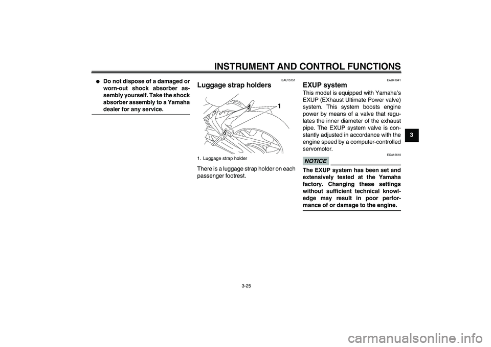
EAU15151
Luggage strap holders There is a luggage strap holder on each
passenger footrest.
EAU41941
EXUP system This model is equipped with Yamaha’s
EXUP (EXhaust Ultimate Power valve)
system. This system boosts engine
power by means of a valve that regu-
lates the inner diameter of the exhaust
pipe. The EXUP system valve is con-
stantly adjusted in accordance with the
engine speed by a computer-controlled
servomotor.NOTICE
ECA15610
The EXUP system has been set and
extensively tested at the Yamaha
factory. Changing these settings
without sufficient technical knowl-
edge may result in poor perfor-
mance of or damage to the engine.
1. Luggage strap holder
U3C3E4E0.book Page 25 Friday, July 10, 2009 5:01 PM
Page 45 of 102

OPERATION AND IMPORTANT RIDING POINTS
5-1
5
EAU15951
Read the Owner’s Manual carefully to
become familiar with all controls. If
there is a control or function you do not
understand, ask your Yamaha dealer.
WARNING
EWA10271
Failure to familiarize yourself with
the controls can lead to loss of con-
trol, which could cause an accident
or injury.
EAU48020
TIPThis model is equipped with a lean an-
gle sensor to stop the engine in case of
a turnover. In this case, the multi-func-
tion display indicates error code 30, but
this is not a malfunction. Turn the key to
“OFF” and then to “ON” to clear the er-
ror code. Failing to do so will prevent
the engine from starting even though
the engine will crank when pushing the
start switch.
EAU44726
Starting the engine In order for the ignition circuit cut-off
system to enable starting, one of the
following conditions must be met.�
The transmission is in the neutral
position.
�
The transmission is in gear with
the clutch lever pulled and the sid-
estand up.
See page 3-26 for more informa-
tion.
1. Turn the key to “ON” and make
sure that the engine stop switch is
set to“”.
The following warning lights and
indicator light should come on for a
few seconds, then go off.�
Oil level warning light
�
Coolant temperature warning
light
�
Engine trouble warning light
�
ABS warning light (for ABS
models)
�
Immobilizer system indicator
light
U3C3E4E0.book Page 1 Friday, July 10, 2009 5:01 PM
Page 52 of 102

PERIODIC MAINTENANCE AND ADJUSTMENT
6-4
6
10 Drive chainCheck chain slack, alignment and
condition.
Adjust and lubricate chain with a
special O-ring chain lubricant
thoroughly.Every 1000 km (600 mi) and after washing the motorcycle, riding in the rain or
riding in wet areas
11*Steering bearingsCheck bearing play and steering
for roughness.√√√√√
Lubricate with lithium-soap-based
grease.Every 20000 km (12000 mi)
12*Chassis fastenersMake sure that all nuts, bolts and
screws are properly tightened.√√√√√
13Brake lever pivot
shaftLubricate with silicone grease.√√√√√
14Brake pedal pivot
shaftLubricate with lithium-soap-based
grease.√√√√√
15Clutch lever pivot
shaftLubricate with lithium-soap-based
grease.√√√√√
16Shift pedal pivot
shaftLubricate with lithium-soap-based
grease.√√√√√
17Sidestand, center-
standCheck operation.
Lubricate.√√√√√
18*Sidestand switchCheck operation.√√√√√√
19*Front forkCheck operation and for oil leak-
age.√√√√
20*Shock absorber as-
semblyCheck operation and shock ab-
sorber for oil leakage.√√√√ NO. ITEM CHECK OR MAINTENANCE JOBODOMETER READING
ANNUAL
CHECK 1000 km
(600 mi)10000 km
(6000 mi)20000 km
(12000 mi)30000 km
(18000 mi)40000 km
(24000 mi)U3C3E4E0.book Page 4 Friday, July 10, 2009 5:01 PM
Page 70 of 102
Rear brake (FZ1-SA)
Insufficient brake fluid may allow air to
enter the brake system, p")
PERIODIC MAINTENANCE AND ADJUSTMENT
6-22
6
EAU43111
Checking the brake fluid level Front brake
Rear brake (FZ1-S)Rear brake (FZ1-SA)
Insufficient brake fluid may allow air to
enter the brake system, possibly caus-
ing it to become ineffective.
Before riding, check that the brake fluid
is above the minimum level mark and
replenish if necessary. A low brake fluid
level may indicate worn brake pads
and/or brake system leakage. If the
brake fluid level is low, be sure to check
the brake pads for wear and the brake
system for leakage.
TIPThe rear brake fluid reservoir is located
behind panel C. (See page 6-7.)Observe these precautions:
�
When checking the fluid level,
make sure that the top of the brake
fluid reservoir is level.
�
Use only the recommended quality
brake fluid, otherwise the rubber
seals may deteriorate, causing
leakage and poor braking perfor-
mance.
�
Refill with the same type of brake
fluid. Mixing fluids may result in a
harmful chemical reaction and
lead to poor braking performance.
�
Be careful that water does not en-
ter the brake fluid reservoir when
refilling. Water will significantly
lower the boiling point of the fluid
and may result in vapor lock, and
dirt may clog the ABS hydraulic
unit valves.
�
Brake fluid may deteriorate paint-
ed surfaces or plastic parts. Al-
ways clean up spilled fluid
immediately.
1. Minimum level mark
1. Minimum level mark
1. Minimum level mark
Recommended brake fluid:
DOT 4
U3C3E4E0.book Page 22 Friday, July 10, 2009 5:01 PM
Page 79 of 102
PERIODIC MAINTENANCE AND ADJUSTMENT
6-31
6 FZ1-SA FZ1-S FZ1-SA
If a fuse is blown, replace it as follows.
TIPInclude steps 2 and 6 only for the fuel
injection system fuse.1. Turn the key to “OFF” and turn off
the electrical circuit in question.
1. Main fuse
2. Fuse box
3. Fuel injection system fuse
4. Fuel injection system spare fuse
1. Fuse box
2. Ignition fuse
3. Signaling system fuse
4. Taillight fuse
5. Backup fuse (for clock and immobilizer sys-
tem)
6. Right radiator fan fuse
7. Left radiator fan fuse
8. Headlight fuse
9. Spare fuse
1. Ignition fuse
2. Signaling system fuse
3. Taillight fuse
4. Backup fuse (for clock and immobilizer sys-
tem)
5. Right radiator fan fuse
6. Left radiator fan fuse
7. Spare fuse
8. ABS motor spare fuse
9. ABS control unit fuse
10.Headlight fuse
11.ABS motor fuse
U3C3E4E0.book Page 31 Friday, July 10, 2009 5:01 PM
Page 80 of 102

PERIODIC MAINTENANCE AND ADJUSTMENT
6-32
62. Unhook the battery band, and then
remove the battery cover.
3. Remove the blown fuse, and then
install a new fuse of the specified
amperage. WARNING! Do notuse a fuse of a higher amperage
rating than recommended to
avoid causing extensive dam-
age to the electrical system and
possibly a fire.
[EWA15131]
4. Turn the key to “ON” and turn on
the electrical circuit in question to
check if the device operates.5. If the fuse immediately blows
again, have a Yamaha dealer
check the electrical system.
6. Install the battery cover, and then
hook the battery band onto the
holder.
1. Battery band
2. Battery cover
1. Fuel injection system fuse
2. Fuel injection system spare fuse
Specified fuses:
Main fuse:
50.0 A
Headlight fuse:
25.0 A
Signaling system fuse:
10.0 A
Ignition fuse:
15.0 A
Fuel injection system fuse:
15.0 A
Taillight fuse:
10.0 A
Radiator fan fuse:
10.0 A × 2
Backup fuse:
10.0 A
ABS control unit fuse:
FZ1-SA 10.0 A
ABS motor fuse:
FZ1-SA 30.0 A
U3C3E4E0.book Page 32 Friday, July 10, 2009 5:01 PM