Page 78 of 104

PERIODIC MAINTENANCE AND ADJUSTMENT
6-29
6
NOTICE
ECA16520
To charge a VRLA (Valve Regulated
Lead Acid) battery, a special (con-
stant-voltage) battery charger is re-
quired. Using a conventional battery
charger will damage the battery. If
you do not have access to a con-
stant-voltage battery charger, have a
Yamaha dealer charge your battery.To store the battery
1. If the vehicle will not be used for
more than one month, remove the
battery, fully charge it, and then
place it in a cool, dry place.
NOTICE: When removing the
battery, be sure the key is
turned to “OFF”, then discon-
nect the negative lead before
disconnecting the positive lead.
[ECA16302]
2. If the battery will be stored for more
than two months, check it at least
once a month and fully charge it if
necessary.
3. Fully charge the battery before in-
stallation.4. After installation, make sure that
the battery leads are properly con-
nected to the battery terminals.
NOTICE
ECA16530
Always keep the battery charged.
Storing a discharged battery can
cause permanent battery damage.
EAU43132
Replacing the fuses The main fuse, the fuel injection system
fuse, and the fuse boxes, which contain
the fuses for the individual circuits, are
located under the rider seat. (See page
3-19.)
FZ1-N1. Main fuse
2. Fuse box
3. Fuel injection system fuse
4. Fuel injection system spare fuse
U2D1E4E0.book Page 29 Tuesday, July 7, 2009 7:05 PM
Page 79 of 104
PERIODIC MAINTENANCE AND ADJUSTMENT
6-30
6 FZ1-NA FZ1-N FZ1-NA
If a fuse is blown, replace it as follows.
TIPInclude steps 2 and 6 only for the fuel
injection system fuse.1. Turn the key to “OFF” and turn off
the electrical circuit in question.
1. Main fuse
2. Fuse box
3. Fuel injection system fuse
4. Fuel injection system spare fuse
1. Fuse box
2. Ignition fuse
3. Signaling system fuse
4. Taillight fuse
5. Backup fuse (for clock and immobilizer sys-
tem)
6. Right radiator fan fuse
7. Left radiator fan fuse
8. Headlight fuse
9. Spare fuse
1. Ignition fuse
2. Signaling system fuse
3. Taillight fuse
4. Backup fuse (for clock and immobilizer sys-
tem)
5. Right radiator fan fuse
6. Left radiator fan fuse
7. Spare fuse
8. ABS motor spare fuse
9. ABS control unit fuse
10.Headlight fuse
11.ABS motor fuse
U2D1E4E0.book Page 30 Tuesday, July 7, 2009 7:05 PM
Page 80 of 104
PERIODIC MAINTENANCE AND ADJUSTMENT
6-31
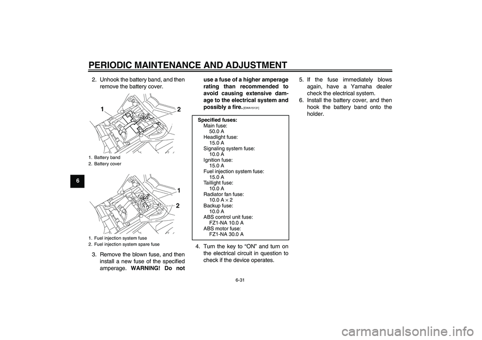
62. Unhook the battery band, and then
remove the battery cover.
3. Remove the blown fuse, and then
install a new fuse of the specified
amperage. WARNING! Do notuse a fuse of a higher amperage
rating than recommended to
avoid causing extensive dam-
age to the electrical system and
possibly a fire.
[EWA15131]
4. Turn the key to “ON” and turn on
the electrical circuit in question to
check if the device operates.5. If the fuse immediately blows
again, have a Yamaha dealer
check the electrical system.
6. Install the battery cover, and then
hook the battery band onto the
holder.
1. Battery band
2. Battery cover
1. Fuel injection system fuse
2. Fuel injection system spare fuse
Specified fuses:
Main fuse:
50.0 A
Headlight fuse:
15.0 A
Signaling system fuse:
10.0 A
Ignition fuse:
15.0 A
Fuel injection system fuse:
15.0 A
Taillight fuse:
10.0 A
Radiator fan fuse:
10.0 A × 2
Backup fuse:
10.0 A
ABS control unit fuse:
FZ1-NA 10.0 A
ABS motor fuse:
FZ1-NA 30.0 A
U2D1E4E0.book Page 31 Tuesday, July 7, 2009 7:05 PM
Page 81 of 104
PERIODIC MAINTENANCE AND ADJUSTMENT
6-32
6
EAU34384
Replacing the headlight bulb This model is equipped with a quartz
bulb headlight. If the headlight bulb
burns out, replace it as follows.NOTICE
ECA10650
Take care not to damage the follow-
ing parts:�
Headlight bulb
Do not touch the glass part of
the headlight bulb to keep it free
from oil, otherwise the transpar-
ency of the glass, the luminosity
of the bulb, and the bulb life will
be adversely affected. Thor-
oughly clean off any dirt and fin-
gerprints on the headlight bulb
using a cloth moistened with al-
cohol or thinner.
�
Headlight lens
Do not affix any type of tinted
film or stickers to the headlight
lens.
Do not use a headlight bulb of a
wattage higher than specified.
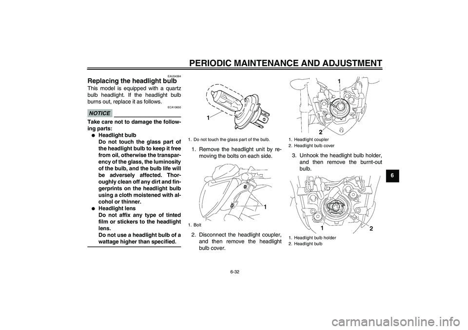
1. Remove the headlight unit by re-
moving the bolts on each side.
2. Disconnect the headlight coupler,
and then remove the headlight
bulb cover.3. Unhook the headlight bulb holder,
and then remove the burnt-out
bulb.1. Do not touch the glass part of the bulb.
1. Bolt
1. Headlight coupler
2. Headlight bulb cover
1. Headlight bulb holder
2. Headlight bulb
U2D1E4E0.book Page 32 Tuesday, July 7, 2009 7:05 PM
Page 82 of 104
PERIODIC MAINTENANCE AND ADJUSTMENT
6-33
64. Place a new headlight bulb into po-
sition, and then secure it with the
bulb holder.
5. Install the headlight bulb cover,
and then connect the coupler.
6. Install the headlight unit by install-
ing the bolts.
7. Have a Yamaha dealer adjust the
headlight beam if necessary.
EAU24114
Replacing the tail/brake light
bulb 1. Remove the passenger seat. (See
page 3-19.)
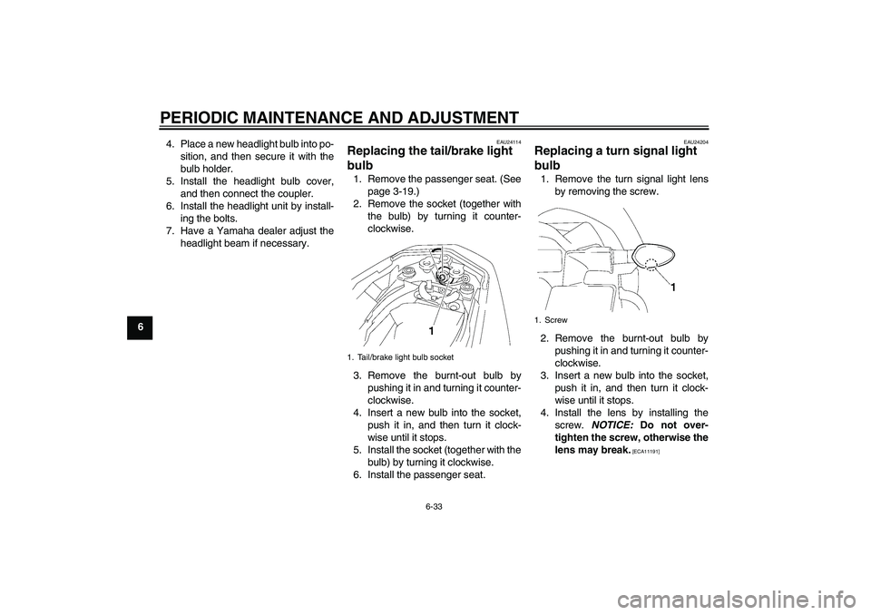
2. Remove the socket (together with
the bulb) by turning it counter-
clockwise.
3. Remove the burnt-out bulb by
pushing it in and turning it counter-
clockwise.
4. Insert a new bulb into the socket,
push it in, and then turn it clock-
wise until it stops.
5. Install the socket (together with the
bulb) by turning it clockwise.
6. Install the passenger seat.
EAU24204
Replacing a turn signal light
bulb 1. Remove the turn signal light lens
by removing the screw.
2. Remove the burnt-out bulb by
pushing it in and turning it counter-
clockwise.
3. Insert a new bulb into the socket,
push it in, and then turn it clock-
wise until it stops.
4. Install the lens by installing the
screw. NOTICE: Do not over-
tighten the screw, otherwise the
lens may break.
[ECA11191]
1. Tail/brake light bulb socket
1. Screw
U2D1E4E0.book Page 33 Tuesday, July 7, 2009 7:05 PM
Page 83 of 104
PERIODIC MAINTENANCE AND ADJUSTMENT
6-34
6
EAU24312
Replacing the license plate
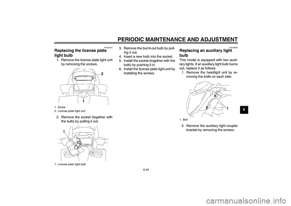
light bulb 1. Remove the license plate light unit
by removing the screws.
2. Remove the socket (together with
the bulb) by pulling it out.3. Remove the burnt-out bulb by pull-
ing it out.
4. Insert a new bulb into the socket.
5. Install the socket (together with the
bulb) by pushing it in.
6. Install the license plate light unit by
installing the screws.
EAU39383
Replacing an auxiliary light
bulb This model is equipped with two auxil-
iary lights. If an auxiliary light bulb burns
out, replace it as follows.
1. Remove the headlight unit by re-
moving the bolts on each side.
2. Remove the auxiliary light coupler
bracket by removing the screws.
1. Screw
2. License plate light unit
1. License plate light bulb
1. Bolt
U2D1E4E0.book Page 34 Tuesday, July 7, 2009 7:05 PM
Page 84 of 104
PERIODIC MAINTENANCE AND ADJUSTMENT
6-35
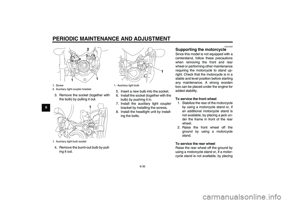
63. Remove the socket (together with
the bulb) by pulling it out.
4. Remove the burnt-out bulb by pull-
ing it out.5. Insert a new bulb into the socket.
6. Install the socket (together with the
bulb) by pushing it in.
7. Install the auxiliary light coupler
bracket by installing the screws.
8. Install the headlight unit by install-
ing the bolts.
EAU24350
Supporting the motorcycle Since this model is not equipped with a
centerstand, follow these precautions
when removing the front and rear
wheel or performing other maintenance
requiring the motorcycle to stand up-
right. Check that the motorcycle is in a
stable and level position before starting
any maintenance. A strong wooden
box can be placed under the engine for
added stability.
To service the front wheel
1. Stabilize the rear of the motorcycle
by using a motorcycle stand or, if
an additional motorcycle stand is
not available, by placing a jack un-
der the frame in front of the rear
wheel.
2. Raise the front wheel off the
ground by using a motorcycle
stand.
To service the rear wheel
Raise the rear wheel off the ground by
using a motorcycle stand or, if a motor-
cycle stand is not available, by placing
1. Screw
2. Auxiliary light coupler bracket
1. Auxiliary light bulb socket
1. Auxiliary light bulb
U2D1E4E0.book Page 35 Tuesday, July 7, 2009 7:05 PM
Page 85 of 104
PERIODIC MAINTENANCE AND ADJUSTMENT
6-36
6 a jack either under each side of the
frame in front of the rear wheel or under
each side of the swingarm.
EAU44790
Front wheel (FZ1-N)
WARNING
EWA14840
For the ABS model, have a Yamaha
dealer remove and install the wheel.
EAU39392
To remove the front wheel
WARNING
EWA10821
To avoid injury, securely support the
vehicle so there is no danger of it
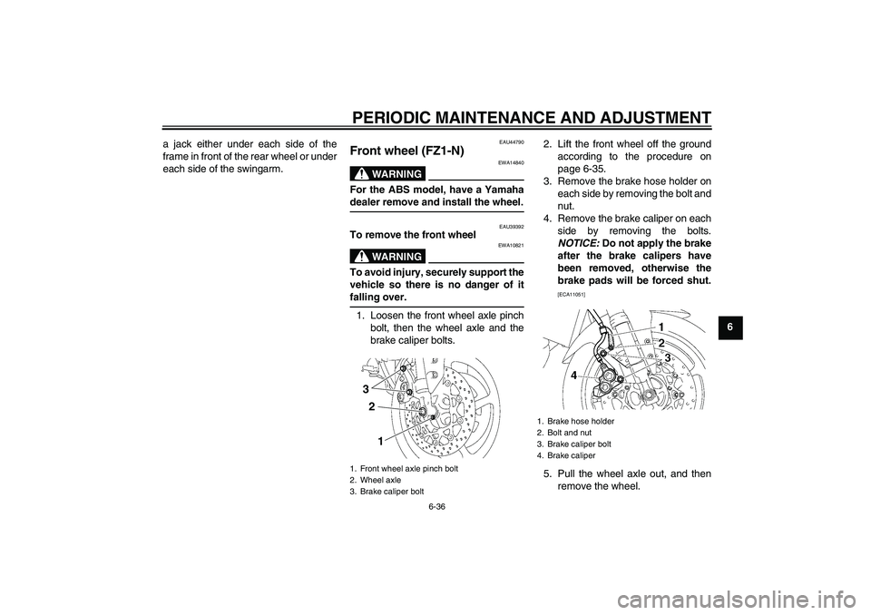
falling over.1. Loosen the front wheel axle pinch
bolt, then the wheel axle and the
brake caliper bolts.2. Lift the front wheel off the ground
according to the procedure on
page 6-35.
3. Remove the brake hose holder on
each side by removing the bolt and
nut.
4. Remove the brake caliper on each
side by removing the bolts.
NOTICE: Do not apply the brake
after the brake calipers have
been removed, otherwise the
brake pads will be forced shut.
[ECA11051]
5. Pull the wheel axle out, and then
remove the wheel.
1. Front wheel axle pinch bolt
2. Wheel axle
3. Brake caliper bolt
3
2
1
1. Brake hose holder
2. Bolt and nut
3. Brake caliper bolt
4. Brake caliper
U2D1E4E0.book Page 36 Tuesday, July 7, 2009 7:05 PM