Page 7 of 106

TABLE OF CONTENTS
Checking and lubricating the
brake lever ................................ 6-25
Checking and lubricating the
centerstand and sidestand ........ 6-26
Lubricating the swingarm pivots ... 6-26
Lubricating the rear suspension ... 6-27
Checking the front fork ................. 6-27
Checking the steering ................... 6-28
Checking the wheel bearings ....... 6-28
Battery .......................................... 6-28
Replacing the fuses ...................... 6-30
Headlight bulb .............................. 6-31
Front turn signal light .................... 6-32
Replacing a rear turn signal light
bulb or a tail/brake light bulb ..... 6-32
Replacing the license plate light
bulb ........................................... 6-33
Auxiliary light bulb ........................ 6-33
Troubleshooting ............................ 6-34
Troubleshooting charts ................. 6-35
MOTORCYCLE CARE AND
STORAGE.......................................... 7-1
Matte color caution ......................... 7-1
Care ................................................ 7-1
Storage ...........................................7-3
SPECIFICATIONS ............................. 8-1
CONSUMER INFORMATION............. 9-1
Identification numbers .................... 9-1
U1DAE0E0.book Page 2 Friday, January 15, 2010 4:03 PM
Page 13 of 106
DESCRIPTION
2-2
2
EAU10420
Right view
12
3,4
5
6
78
9
10
11
1. Storage compartment (page 3-26)
2. Fuel tank cap (page 3-20)
3. Fuse box (page 6-30)
4. ABS motor fuse (page 6-30)
5. Windshield (page 3-15)
6. Battery (page 6-28)
7. Main fuse (page 6-30)
8. Front fork compression damping force adjusting screw (page 3-30)9. Brake pedal (page 3-19)
10.Shock absorber assembly rebound damping force adjusting knob
(page 3-31)
11.Rear brake fluid reservoir (page 6-22)
U1DAE0E0.book Page 2 Friday, January 15, 2010 4:03 PM
Page 18 of 106

The steering is locked, and th")
INSTRUMENT AND CONTROL FUNCTIONS
3-4
3To unlock the steering
Push the key into the main switch, and
then turn it to “OFF” while still pushing
it.
EAU39460
(Parking)
The steering is locked, and the tail-
lights, license plate light and auxiliary
lights are on. The hazard lights and turn
signal lights can be turned on, but all
other electrical systems are off. The
key can be removed.
The steering must be locked before the
key can be turned to“”.
NOTICE
ECA11020
Do not use the parking position for
an extended length of time, other-
wise the battery may discharge.
EAU11004
Indicator and warning lights
EAU11030
Turn signal indicator lights“”
and“”
The corresponding indicator light flash-
es when the turn signal switch is
pushed to the left or right.
1. Push.
2. Turn.
1. Left turn signal indicator light“”
2. Right turn signal indicator light“”
3. Engine trouble“”/YCC-S “SHIFT” indica-
tors and warning light
4. Anti-lock Brake System (ABS) warning
light“”
5. Neutral indicator light“”
6. High beam indicator light“”
7. Oil level warning light“”
8. Immobilizer system indicator light
ABS
U1DAE0E0.book Page 4 Friday, January 15, 2010 4:03 PM
Page 41 of 106
INSTRUMENT AND CONTROL FUNCTIONS
3-27
3
�
Do not exceed the maximum
load of 208 kg (459 lb) for the ve-
hicle.
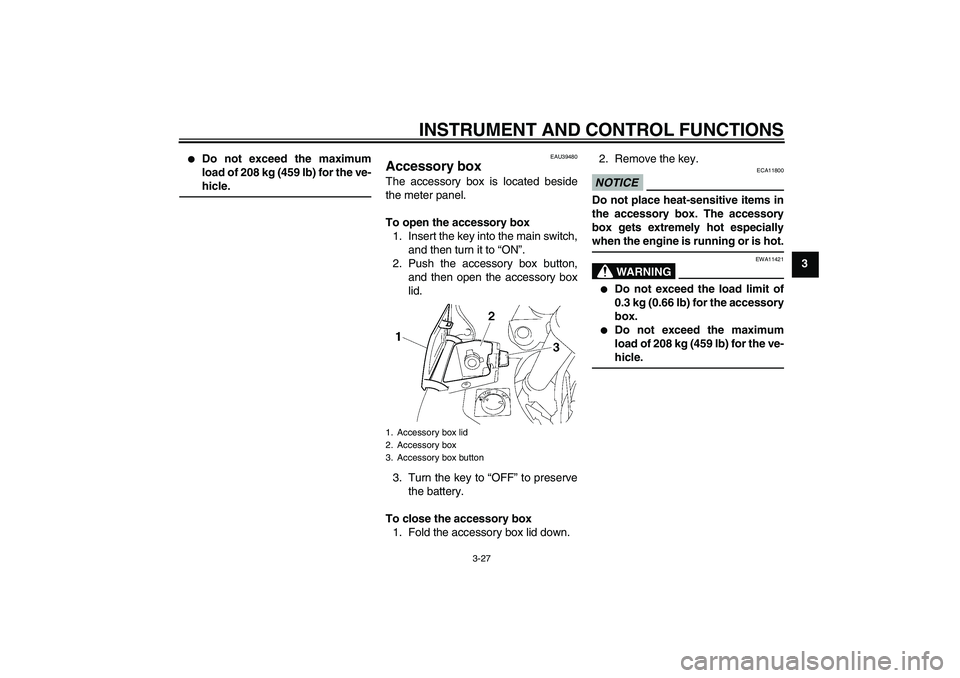
EAU39480
Accessory box The accessory box is located beside
the meter panel.
To open the accessory box
1. Insert the key into the main switch,
and then turn it to “ON”.
2. Push the accessory box button,
and then open the accessory box
lid.
3. Turn the key to “OFF” to preserve
the battery.
To close the accessory box
1. Fold the accessory box lid down.2. Remove the key.
NOTICE
ECA11800
Do not place heat-sensitive items in
the accessory box. The accessory
box gets extremely hot especially
when the engine is running or is hot.
WARNING
EWA11421
�
Do not exceed the load limit of
0.3 kg (0.66 lb) for the accessory
box.
�
Do not exceed the maximum
load of 208 kg (459 lb) for the ve-
hicle.
1. Accessory box lid
2. Accessory box
3. Accessory box button
U1DAE0E0.book Page 27 Friday, January 15, 2010 4:03 PM
Page 50 of 106

INSTRUMENT AND CONTROL FUNCTIONS
3-36
3
EAU39653
Auxiliary DC jack NOTICE
ECA15431
The accessory connected to the
auxiliary DC jack should not be used
with the engine turned off, and the
load must never exceed 30 W (2.5 A),
otherwise the fuse may blow or the
battery may discharge.
WARNING
EWA14360
To prevent electrical shock or short-
circuiting, make sure that the cap is
installed when the auxiliary DC jack
is not being used.This vehicle is equipped with an auxilia-
ry DC jack in the accessory box.
A 12-V accessory connected to the
auxiliary jack can be used when the key
is in the “ON” position and should only
be used when the engine is running.
To use the auxiliary DC jack
1. Open the accessory box lid. (See
page 3-27.)
2. Turn the key to “OFF”.
3. Remove the auxiliary DC jack cap.4. Insert the accessory plug into the
auxiliary DC jack.
5. Turn the key to “ON”, and then
start the engine. (See page 5-1.)
1. Auxiliary DC jack cap
1. Auxiliary DC jack
U1DAE0E0.book Page 36 Friday, January 15, 2010 4:03 PM
Page 86 of 106

PERIODIC MAINTENANCE AND ADJUSTMENT
6-28
6
EAU45511
Checking the steering Worn or loose steering bearings may
cause danger. Therefore, the operation
of the steering must be checked as fol-
lows at the intervals specified in the pe-
riodic maintenance and lubrication
chart.
1. Place the vehicle on the center-
stand. WARNING! To avoid inju-
ry, securely support the vehicle
so there is no danger of it falling
over.
[EWA10751]
2. Hold the lower ends of the front
fork legs and try to move them for-
ward and backward. If any free
play can be felt, have a Yamaha
dealer check or repair the steering.
EAU23291
Checking the wheel bearings The front and rear wheel bearings must
be checked at the intervals specified in
the periodic maintenance and lubrica-
tion chart. If there is play in the wheel
hub or if the wheel does not turn
smoothly, have a Yamaha dealer check
the wheel bearings.
EAU39524
Battery The battery is located under panel A.
(See page 6-7.)
This model is equipped with a VRLA
(Valve Regulated Lead Acid) battery.
There is no need to check the electro-
lyte or to add distilled water. However,
the battery lead connections need to be
checked and, if necessary, tightened.
WARNING
EWA10760
�
Electrolyte is poisonous and
dangerous since it contains sul-
furic acid, which causes severe
burns. Avoid any contact with
1. Battery
2. Positive battery lead (red)
3. Negative battery lead (black)
U1DAE0E0.book Page 28 Friday, January 15, 2010 4:03 PM
Page 87 of 106

PERIODIC MAINTENANCE AND ADJUSTMENT
6-29
6 skin, eyes or clothing and al-
ways shield your eyes when
working near batteries. In case
of contact, administer the fol-
lowing FIRST AID.
EXTERNAL: Flush with plenty
of water.
INTERNAL: Drink large quan-
tities of water or milk and im-
mediately call a physician.
EYES: Flush with water for 15
minutes and seek prompt
medical attention.
�
Batteries produce explosive hy-
drogen gas. Therefore, keep
sparks, flames, cigarettes, etc.,
away from the battery and pro-
vide sufficient ventilation when
charging it in an enclosed
space.
�
KEEP THIS AND ALL BATTER-
IES OUT OF THE REACH OF
CHILDREN.
To charge the battery
Have a Yamaha dealer charge the bat-
tery as soon as possible if it seems to
have discharged. Keep in mind that thebattery tends to discharge more quickly
if the vehicle is equipped with optional
electrical accessories.
NOTICE
ECA16520
To charge a VRLA (Valve Regulated
Lead Acid) battery, a special (con-
stant-voltage) battery charger is re-
quired. Using a conventional battery
charger will damage the battery. If
you do not have access to a con-
stant-voltage battery charger, have a
Yamaha dealer charge your battery.To store the battery
1. If the vehicle will not be used for
more than one month, remove the
battery, fully charge it, and then
place it in a cool, dry place.
NOTICE: When removing the
battery, be sure the key is
turned to “OFF”, then discon-
nect the negative lead before
disconnecting the positive lead.
[ECA16302]
2. If the battery will be stored for more
than two months, check it at least
once a month and fully charge it if
necessary.3. Fully charge the battery before in-
stallation.
4. After installation, make sure that
the battery leads are properly con-
nected to the battery terminals.
NOTICE
ECA16530
Always keep the battery charged.
Storing a discharged battery can
cause permanent battery damage.
U1DAE0E0.book Page 29 Friday, January 15, 2010 4:03 PM
Page 93 of 106

PERIODIC MAINTENANCE AND ADJUSTMENT
6-35
6
EAU42501
Troubleshooting charts Starting problems or poor engine performance
Check the fuel level in
the fuel tank.1. Fuel
There is enough fuel.
There is no fuel.
Check the compression.
Supply fuel.
The engine does not start.
Check the compression.
Operate the electric starter.2. Compression
There is compression.
There is no compression.
Check the ignition.
Have a Yamaha dealer
check the vehicle.
Remove the spark plugs
and check the electrodes.3. Ignition
Wipe off with a dry cloth and correct the
spark plug gaps, or replace the spark plugs.
Have a Yamaha dealer check the vehicle.
The engine does not start.
Have a Yamaha dealer
check the vehicle.
The engine does not start.
Check the battery.
Operate the electric starter.4. Battery
The engine turns over
quickly.
The engine turns over
slowly.
The battery is good.Check the battery lead connections,
and charge the battery if necessary.
DryWet
Operate the electric starter.
U1DAE0E0.book Page 35 Friday, January 15, 2010 4:03 PM

2. Fuel tank cap (page 3-20)
3. Fuse box (page 6-30)
4. ABS motor fuse (page 6-30)
5. Windshield (page 3-")