Page 36 of 106

INSTRUMENT AND CONTROL FUNCTIONS
3-22
3or premium unleaded fuel. Use of un-
leaded fuel will extend spark plug life
and reduce maintenance costs.
EAU39451
Fuel tank breather/overflow
hose Before operating the motorcycle:�
Check the fuel tank breather/over-
flow hose connection.
�
Check the fuel tank breather/over-
flow hose for cracks or damage,
and replace it if damaged.
�
Make sure that the end of the fuel
tank breather/overflow hose is not
blocked, and clean it if necessary.
EAU13445
Catalytic converters This vehicle is equipped with catalytic
converters in the exhaust system.
WARNING
EWA10862
The exhaust system is hot after op-
eration. To prevent a fire hazard or
burns:�
Do not park the vehicle near
possible fire hazards such as
grass or other materials that
easily burn.
�
Park the vehicle in a place
where pedestrians or children
are not likely to touch the hot
exhaust system.
�
Make sure that the exhaust sys-
tem has cooled down before do-
ing any maintenance work.
�
Do not allow the engine to idle
more than a few minutes. Long
idling can cause a build-up of
heat.
1. Fuel tank breather/overflow hose
U1DAE0E0.book Page 22 Friday, January 15, 2010 4:03 PM
Page 41 of 106
INSTRUMENT AND CONTROL FUNCTIONS
3-27
3
�
Do not exceed the maximum
load of 208 kg (459 lb) for the ve-
hicle.
EAU39480
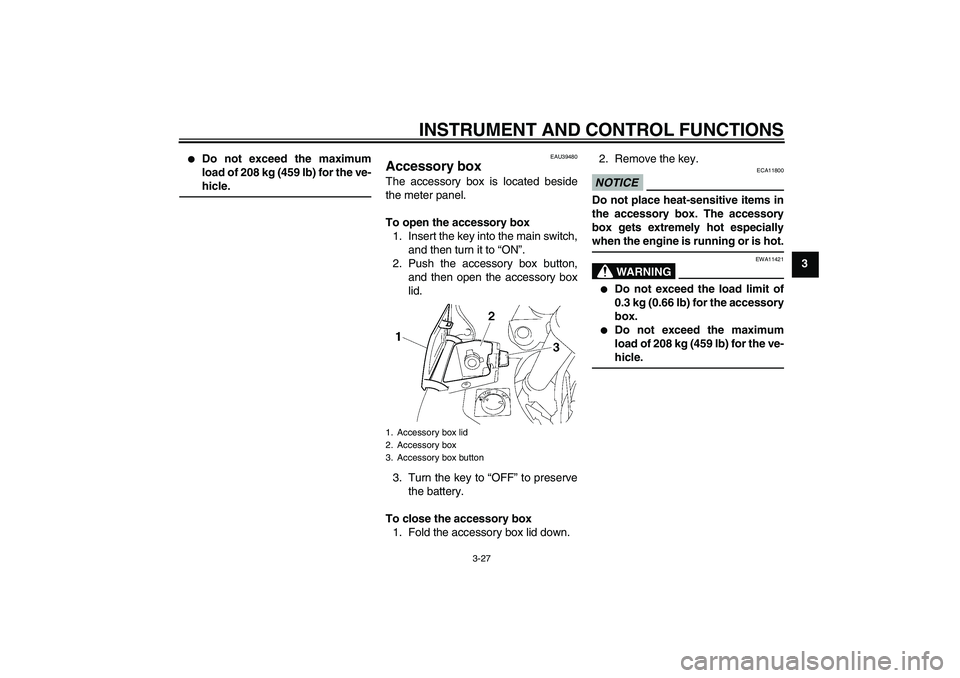
Accessory box The accessory box is located beside
the meter panel.
To open the accessory box
1. Insert the key into the main switch,
and then turn it to “ON”.
2. Push the accessory box button,
and then open the accessory box
lid.
3. Turn the key to “OFF” to preserve
the battery.
To close the accessory box
1. Fold the accessory box lid down.2. Remove the key.
NOTICE
ECA11800
Do not place heat-sensitive items in
the accessory box. The accessory
box gets extremely hot especially
when the engine is running or is hot.
WARNING
EWA11421
�
Do not exceed the load limit of
0.3 kg (0.66 lb) for the accessory
box.
�
Do not exceed the maximum
load of 208 kg (459 lb) for the ve-
hicle.
1. Accessory box lid
2. Accessory box
3. Accessory box button
U1DAE0E0.book Page 27 Friday, January 15, 2010 4:03 PM
Page 47 of 106

INSTRUMENT AND CONTROL FUNCTIONS
3-33
3
EAU40502
Grip warmer adjusting knob
WARNING
EWA14510
Do not turn the grip warmer knob
while the vehicle is moving.NOTICE
ECA15520
�
Be sure to wear gloves when us-
ing the grip warmers.
�
If the ambient temperature is 20
°C (68 °F) or higher, do not set
the grip warmer adjusting knob
to the “HI” position.
�
If the handlebar grip or throttle
grip becomes worn or damaged,
stop using the grip warmers and
replace the grips.
This vehicle is equipped with grip
warmers, which can only be used when
the engine is running.
Use the grip warmer adjusting knob, lo-
cated near the accessory box, to adjust
the grip warmer temperature.The grip warmer adjusting knob can be
set between the “LO” and “HI” posi-
tions. To raise the temperature, turn the
knob in direction (a). To lower the tem-
perature, turn the knob in direction (b).
Align the“” mark on the knob with
“OFF” to turn the grip warmers off.
TIPWhen the vehicle is stopped or travel-
ing at extremely low speeds (e.g., in
traffic jams), the grip warmer tempera-
ture is lower than when traveling at
higher speeds.
EAU15303
Sidestand The sidestand is located on the left side
of the frame. Raise the sidestand or
lower it with your foot while holding the
vehicle upright.TIPThe built-in sidestand switch is part of
the ignition circuit cut-off system, which
cuts the ignition in certain situations.
(See page 3-34 for an explanation of
the ignition circuit cut-off system.)
WARNING
EWA10240
The vehicle must not be ridden with
the sidestand down, or if the side-
stand cannot be properly moved up
(or does not stay up), otherwise the
sidestand could contact the ground
and distract the operator, resulting
in a possible loss of control.
Yamaha’s ignition circuit cut-off
system has been designed to assist
the operator in fulfilling the respon-
sibility of raising the sidestand be-
fore starting off. Therefore, check
this system regularly as described
1.“LO” position
2.“OFF” position
3.“” mark
4. Grip warmer adjusting knob
5.“HI” position
U1DAE0E0.book Page 33 Friday, January 15, 2010 4:03 PM
Page 48 of 106
INSTRUMENT AND CONTROL FUNCTIONS
3-34
3below and have a Yamaha dealer re-
pair it if it does not function proper-
ly.
EAU40524
Ignition circuit cut-off system The ignition circuit cut-off system (com-
prising the sidestand switch and brake
light switches) has the following func-
tions.�
It prevents starting when the side-
stand is up, but neither brake is ap-
plied.
�
It prevents starting when either
brake is applied, but the sidestand
is still down.
�
It cuts the running engine when the
sidestand is moved down.
Periodically check the operation of the
ignition circuit cut-off system according
to the following procedure.
U1DAE0E0.book Page 34 Friday, January 15, 2010 4:03 PM
Page 49 of 106

INSTRUMENT AND CONTROL FUNCTIONS
3-35
3
With the engine turned off:
1. Move the sidestand down.
2. Make sure that the engine stop switch is set to “
3. Turn the key on.
4. Shift the transmission into the neutral position.
5. Keep the front or rear brake applied.
6. Push the start switch.
Does the engine start?
With the engine still running:
7. Move the sidestand up.
8. Keep the front or rear brake applied.
9. Shift the transmission into gear.
10. Move the sidestand down.
Does the engine stall?
After the engine has stalled:
11. Move the sidestand up.
12. Release the brake.
13. Push the start switch.
Does the engine start?
The system is OK. The vehicle can be ridden.
NO YES YES NO YES NO
The neutral, the brake switch or the YCC-S
system may not be working correctly.
The vehicle should not be ridden until
checked by a Yamaha dealer.
A brake switch may not be working correctly.
The vehicle should not be ridden until
checked by a Yamaha dealer.The sidestand switch may not be working correctly.
The vehicle should not be ridden until
checked by a Yamaha dealer.• The vehicle must be placed on the center-
stand during this inspection.• If a malfunction is noted, have a Yamaha
dealer check the system before riding.
WARNING
”.
U1DAE0E0.book Page 35 Friday, January 15, 2010 4:03 PM
Page 50 of 106

INSTRUMENT AND CONTROL FUNCTIONS
3-36
3
EAU39653
Auxiliary DC jack NOTICE
ECA15431
The accessory connected to the
auxiliary DC jack should not be used
with the engine turned off, and the
load must never exceed 30 W (2.5 A),
otherwise the fuse may blow or the
battery may discharge.
WARNING
EWA14360
To prevent electrical shock or short-
circuiting, make sure that the cap is
installed when the auxiliary DC jack
is not being used.This vehicle is equipped with an auxilia-
ry DC jack in the accessory box.
A 12-V accessory connected to the
auxiliary jack can be used when the key
is in the “ON” position and should only
be used when the engine is running.
To use the auxiliary DC jack
1. Open the accessory box lid. (See
page 3-27.)
2. Turn the key to “OFF”.
3. Remove the auxiliary DC jack cap.4. Insert the accessory plug into the
auxiliary DC jack.
5. Turn the key to “ON”, and then
start the engine. (See page 5-1.)
1. Auxiliary DC jack cap
1. Auxiliary DC jack
U1DAE0E0.book Page 36 Friday, January 15, 2010 4:03 PM
Page 51 of 106

FOR YOUR SAFETY – PRE-OPERATION CHECKS
4-1
4
EAU15596
Inspect your vehicle each time you use it to make sure the vehicle is in safe operating condition. Always follow the inspection
and maintenance procedures and schedules described in the Owner’s Manual.
WARNING
EWA11151
Failure to inspect or maintain the vehicle properly increases the possibility of an accident or equipment damage.
Do not operate the vehicle if you find any problem. If a problem cannot be corrected by the procedures provided in
this manual, have the vehicle inspected by a Yamaha dealer.Before using this vehicle, check the following points:
ITEM CHECKS PAGE
FuelCheck fuel level in fuel tank.
Refuel if necessary.
Check fuel line for leakage.
Check the fuel tank breather/overflow hose for obstructions, cracks or damage,
and check the hose connection.3-21, 3-22
Engine oilCheck oil level in engine.
If necessary, add recommended oil to specified level.
Check vehicle for oil leakage.6-11
Final gear oilCheck vehicle for oil leakage. 6-14
CoolantCheck coolant level in reservoir.
If necessary, add recommended coolant to specified level.
Check cooling system for leakage.6-15
Front brakeCheck operation.
If soft or spongy, have Yamaha dealer bleed hydraulic system.
Check brake pads for wear.
Replace if necessary.
Check fluid level in reservoir.
If necessary, add recommended brake fluid to specified level.
Check hydraulic system for leakage.6-22, 6-22
U1DAE0E0.book Page 1 Friday, January 15, 2010 4:03 PM
Page 54 of 106

OPERATION AND IMPORTANT RIDING POINTS
5-1
5
EAU15951
Read the Owner’s Manual carefully to
become familiar with all controls. If
there is a control or function you do not
understand, ask your Yamaha dealer.
WARNING
EWA10271
Failure to familiarize yourself with
the controls can lead to loss of con-
trol, which could cause an accident
or injury.
EAU46632
TIPThis model is equipped with:�
a lean angle sensor to stop the en-
gine in case of a turnover. In this
case, the multi-function display in-
dicates error code 30, but this is
not a malfunction. Turn the key to
“OFF” and then to “ON” to clear the
error code. Failing to do so will pre-
vent the engine from starting even
though the engine will crank when
pushing the start switch.
�
an engine auto-stop system. The
engine stops automatically if left
idling for 20 minutes. In this case,
the multi-function display indicates
error code 70, but this is not a mal-
function. Push the start switch to
clear the error code and to restart
the engine.
EAU40336
Starting the engine In order for the ignition circuit cut-off
system to enable starting, one of the
following conditions must be met:�
The front or rear brake is applied
with the transmission in the neutral
position whether the sidestand is
up or down.
�
The front or rear brake is applied
with the transmission in gear and
the sidestand is up.
See page 3-34 for more informa-
tion.WARNING
EWA14541
Always apply the front or rear brake
while the main switch is in the “ON”
position and the transmission is in
gear, otherwise the rear wheel will
move freely.1. Turn the key to “ON” and make
sure that the engine stop switch is
set to“”.
The following warning lights, indi-
cator light and indicators should
come on for a few seconds, then
go off.
�
Oil level warning light
U1DAE0E0.book Page 1 Friday, January 15, 2010 4:03 PM