Page 222 of 302

05 During your trip
Emergency towing
05
222
•Maximum distance with front wheels on
ground: 50 miles (80 km).
•While the vehicle is being towed, try to
keep the tow rope taut at all times.
•The vehicle should only be towed in the
forward direction.
NOTE
During towing, ignition mode II should be
used so that the lighting can be switched on.
CAUTION
Vehicles with AWD (All Wheel Drive) with the
front wheels off the ground should not be
towed at speeds above 50 mph (70 km/h) or
for distances longer than 30 miles (50 km).
CAUTION
•Please check with state and local
authorities before attempting this type
of towing, as vehicles being towed are
subject to regulations regarding maxi-
mum towing speed, length and type of
towing device, lighting, etc.
•If the vehicle's battery is dead, do not
attempt to start the vehicle by pushing
or pulling it as this will damage the
three-way catalytic converter(s). The
engine must be jump started using an
auxiliary battery (see page 108).
•If the vehicle is being towed on a flat bed
truck, the towing eyelets must not be
used to pull the vehicle up onto the flat
bed or to secure the vehicle on the flat
bed. Consult the tow truck operator.
Towing vehicles with front wheel drive/
All Wheel Drive
Volvo recommends the use of flat bed equip-
ment.
•If wheel lift equipment must be used,
please use extreme caution to help avoid
damage to the vehicle. In this case, the
vehicle should be towed with the rear
wheels on the ground if at all possible.
•If it is absolutely necessary to tow the vehi-
cle with the front wheels on the ground,please refer to the towing information on
page 221.
CAUTION
•Sling-type equipment applied at the
front will damage radiator and air con-
ditioning lines.
•It is equally important not to use sling-
type equipment at the rear or apply lift-
ing equipment inside the rear wheels;
serious damage to the rear axle may
result.
•If the vehicle is being towed on a flat bed
truck, the towing eyelets must not be
used to secure the vehicle on the flat
bed. Consult the tow truck operator.
Page 229 of 302

06 Maintenance and specifications
Hood and engine compartment
06
229 Opening and closing the hood
G031911
Pull the lever located under the left side of
the dash to release the hood lock.
Lift the hood slightly. Press the release
control (located under the right front edge
of the hood) to the left, and lift the hood
WARNING
Check that the hood locks properly when
closed.
Engine compartment, overview
The appearance of the engine compartment
may vary depending on engine model.
Coolant expansion tank
Power steering fluid reservoir
Engine oil dipstick
Radiator
Filler cap for engine oil
Cover over brake fluid reservoir
Battery
Relay and fuse box
Washer fluid reservoir
Air cleaner
WARNING
The cooling fan may start or continue to
operate (for up to 6 minutes) after the engine
has been switched off.
WARNING
The ignition should always be completely
switched off before performing any opera-
tions in the engine compartment.
The distributor ignition system operates at
very high voltages. Special safety precau-
tions must be followed to prevent injury.
Always turn the ignition off when:
•Replacing distributor ignition compo-
nents e.g. plugs, coil, etc.
•Do not touch any part of the distributor
ignition system while the engine is run-
ning. This may result in unintended
movements and body injury.
Page 234 of 302

06 Maintenance and specifications
Replacing bulbs
06
234* Option/accessory, for more information, see Introduction.
Introduction
All bulb specifications are listed on page 240.
The following bulbs should only be replaced by
a trained and qualified Volvo service techni-
cian:
•Dome lighting
•Reading lights
•Glove compartment lighting
•Turn signals in the door mirror
•Approach lighting in the door mirror
•Brake/fog/taillights
•Rear side parking lights
•Active Bending Lights and LED bulbs
NOTE
For information regarding any other bulbs
not mentioned in this section, please con-
tact your Volvo retailer or a trained and
authorized Volvo service technician.
WARNING
•Active Bending Lights* – due to the high
voltage used by these headlights, these
bulbs should only be replaced by a
trained and qualified Volvo service tech-
nician.
•Turn off the lights and remove the
remote key from the ignition before
changing any bulbs.
Headlight housing
G010325
WARNING
•The engine should not be running when
changing bulbs.
•When changing in the headlight hous-
ing, if the engine has been running just
prior to replacing bulbs, please be
aware that components in the engine
compartment will be hot.
The entire headlight housing must be lifted out
when replacing all front bulbs (except for the
fog lights).
CAUTION
Never touch the glass of bulbs with your fin-
gers. Grease and oils from your fingers
vaporize in the heat and will leave a deposit
on the reflector, which will damage it.
Page 235 of 302

06 Maintenance and specifications
Replacing bulbs
06
��
235
NOTE
•Always switch off the ignition before
starting to replace a bulb.
•The optional Active Bending Light bulbs
contain trace amounts of mercury.
These bulbs should always be disposed
of by a trained and qualified Volvo serv-
ice technician.
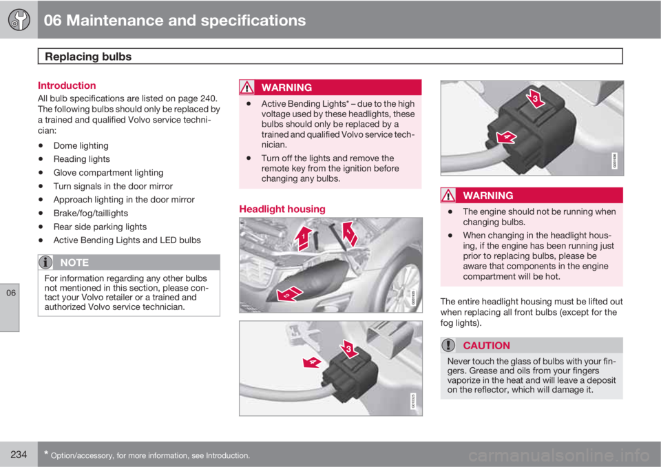
Removing the headlight housing1. Switch off the ignition by pressing quickly
on the START/STOP ENGINE button and
remove the remote key from the ignition
slot
1.
2. (Upper illustration under "Headlight hous-
ing")
Withdraw the headlight housing's lock-
ing pins.
Pull the headlight housing straight out .
CAUTION
When disconnecting the connector, pull on
the connector itself and not on the wiring.
3. (Lower illustration under "Headlight hous-
ing")
Unplug the wiring connector by holding
down the clip with your thumb.
Pull out the connector with the other
hand.
4. Lift out the housing and place it on a soft
surface to avoid scratching the lens.
5. Replace the defective bulb(s).
Reinserting the headlight housing
When reinserting the housing, be sure that the
long locking pin (to the left in the illustration) is
securely in place in both of its retaining clamps.
1. Plug in the connector until it clicks into
place.2. Reinstall the headlight housing and locking
pins. Check that they are correctly
inserted. The headlight housing must be
properly inserted and secured in place
before the lighting is switched on or the
remote key is inserted into the ignition slot.
3. Check that the lights function properly.
The headlight wiring must be connected and
the housing must be securely in place before
the ignition is switched on.
Removing the cover to access the
headlights and parking lights
1Does not apply to vehicles with the optional keyless drive.
Page 242 of 302

06 Maintenance and specifications
Wiper blades and washer fluid
06
242
Wiper blades
The windshield wiper blades are different
lengths. The blade on the driver’s side is longer
than the one on the passenger side.
Service positionThe wiper blades must be in the service (verti-
cal) position for replacement or washing.
1.
Switch off the ignition (ignition mode 0, see
page 79) and keep the remote key in the
ignition slot
1.
2. Move the right steering wheel lever up and
hold it for at least 1 second. The wipers will
then move to the vertical position on the
windshield.The wipers will return to the normal position
when the vehicle is started.
Replacing the windshield wiper blades
With the wipers in the service position, fold
out the wiper arm from the windshield.
Press the button on the wiper blade attach-
ment and pull the wiper blade straight out,
parallel with the wiper arm.
Slide in the new wiper blade until it clicks
into place.
Check that the blade is securely in place.
CleaningKeeping the windshield and wiper blades clean
helps improve visibility and prolongs the serv-
ice life of the wiper blades. Clean the wiper
blades with a stiff-bristle brush and lukewarm
soap solution or car washing detergent.
1Does not apply to vehicles with the optional keyless drive.
Page 245 of 302

06 Maintenance and specifications
Battery
06
��
245
•Never disconnect the battery when the
engine is running, or when the key is in the
ignition. This could damage the vehicle's
electrical system.
•The battery should be disconnected from
the vehicle when a battery charger is used
directly on the battery.
•To help keep the battery in good condition,
the vehicle should be driven for at least 15
minutes a week or connected to a charger
with an automatic charging function.
•If the battery is fully discharged a number
of times, this may shorten its service life.
Keeping the battery fully charged helps
prolong its service life.
•The service life of a battery is affected by
factors such as driving conditions and cli-
mate. Extreme cold may also further
decrease the battery’s starting capacity.
•Because the battery’s starting capacity
decreases with time, it may be necessary
to recharge it if the vehicle is not driven for
an extended period of time or if the vehicle
is usually only driven short distances.
•
CAUTION
•Always use distilled or deionized water
(battery water).
•Never fill above the level mark in the cell.
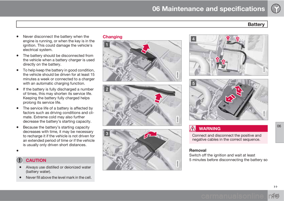
Changing
WARNING
Connect and disconnect the positive and
negative cables in the correct sequence.
RemovalSwitch off the ignition and wait at least
5 minutes before disconnecting the battery so
Page 250 of 302
06 Maintenance and specifications
Fuses
06
250
FunctionA
Starter motor relay30
Ignition coils20
Engine Control Module (ECM),
throttle10
Injection system15
Engine valves10
EVAP/heated oxygen sensor/
Injection15
Crank case ventilation heater20
Fuel leakage detection5
–
-
Cooling fan80
Page 275 of 302

06 Maintenance and specifications
Wheels and tires
06
275
Changing wheels with TPMSPlease note the following when changing or
replacing the factory installed TPMS wheels/
tires on the vehicle:
•Only the factory-mounted wheels are
equipped with TPMS sensors in the valves.
•If the vehicle is equipped with a temporary
spare tire, this tire does not have a TPMS
sensor.
•If wheels without TPMS sensors are moun-
ted on the vehicle, TIRE PRESS SYST
SERVICE REQUIRED will be displayed
each time the vehicle is driven above
25 mph (40 km/h) for 10 minutes or more.
•Once TPMS sensors are properly installed,
the warning message should not reappear.
If the message is still displayed, drive the
vehicle for several minutes at a speed of
20 mph (30 km/h) or faster to erase the
message.
•Volvo recommends that TPMS sensors be
fitted on all wheels used on the vehicle.
Volvo does not recommend moving sen-
sors back and forth between sets of
wheels.
NOTE
•If you change to tires with a different
recommended inflation pressure, the
TPMS system must be recalibrated to
these tires. This must be done by a
trained and qualified Volvo service tech-
nician.
•If a tire is changed, or if the TPMS sen-
sor is moved to another wheel, the sen-
sor's seal, nut, and valve core should be
replaced.
•When installing TPMS sensors, the
vehicle must be parked for at least
15 minutes with the ignition off. if the
vehicle is driven within 15 minutes, a
TPMS error message will be displayed.
CAUTION
When inflating tires with TPMS valves, press
the pump's mouthpiece straight onto the
valve to help avoid bending or otherwise
damaging the valve.