Page 237 of 302

06 Maintenance and specifications
Replacing bulbs
06
��
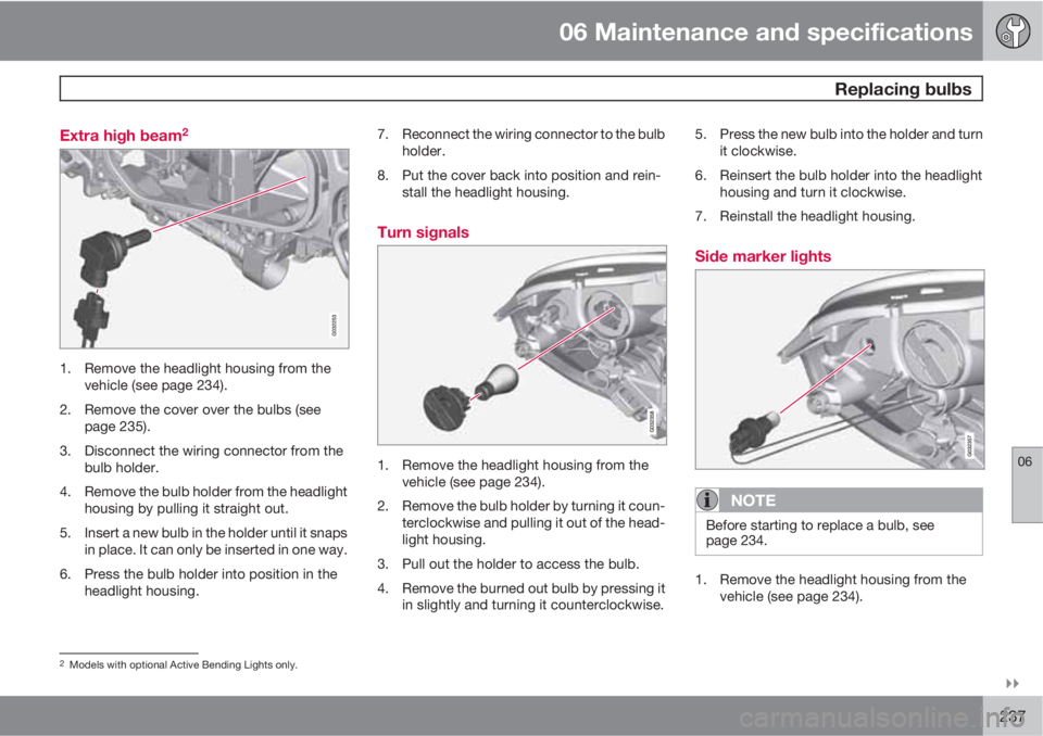
237 Extra high beam
2
1. Remove the headlight housing from the
vehicle (see page 234).
2. Remove the cover over the bulbs (see
page 235).
3. Disconnect the wiring connector from the
bulb holder.
4. Remove the bulb holder from the headlight
housing by pulling it straight out.
5. Insert a new bulb in the holder until it snaps
in place. It can only be inserted in one way.
6. Press the bulb holder into position in the
headlight housing.7. Reconnect the wiring connector to the bulb
holder.
8. Put the cover back into position and rein-
stall the headlight housing.
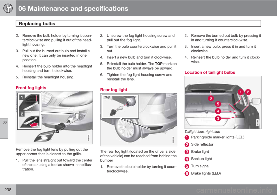
Turn signals
1. Remove the headlight housing from the
vehicle (see page 234).
2. Remove the bulb holder by turning it coun-
terclockwise and pulling it out of the head-
light housing.
3. Pull out the holder to access the bulb.
4. Remove the burned out bulb by pressing it
in slightly and turning it counterclockwise.5. Press the new bulb into the holder and turn
it clockwise.
6. Reinsert the bulb holder into the headlight
housing and turn it clockwise.
7. Reinstall the headlight housing.
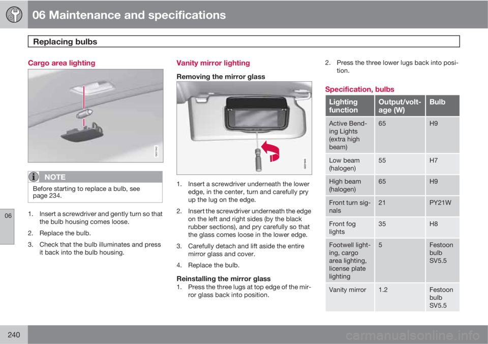
Side marker lights
NOTE
Before starting to replace a bulb, see
page 234.
1. Remove the headlight housing from the
vehicle (see page 234).
2Models with optional Active Bending Lights only.
Page 238 of 302

06 Maintenance and specifications
Replacing bulbs
06
238
2. Remove the bulb holder by turning it coun-
terclockwise and pulling it out of the head-
light housing.
3. Pull out the burned out bulb and install a
new one. It can only be inserted in one
position.
4. Reinsert the bulb holder into the headlight
housing and turn it clockwise.
5. Reinstall the headlight housing.
Front fog lights
Remove the fog light lens by pulling out the
upper corner that is closest to the grille.
1. Pull the lens straight out toward the center
of the car using a tool as shown in the illus-
tration.2. Unscrew the fog light housing screw and
pull out the fog light.
3. Turn the bulb counterclockwise and pull it
out.
4. Insert a new bulb and turn it clockwise.
5.
Reinstall the bulb holder. The TOP mark on
the bulb holder must always be upward.
6. Tighten the fog light housing screw and
reinstall the lens.
Rear fog light
The rear fog light (located on the driver's side
of the vehicle) can be reached from behind the
bumper
1. Remove the bulb holder by turning it coun-
terclockwise.2. Remove the burned out bulb by pressing it
in and turning it counterclockwise.
3. Insert a new bulb, press it in and turn it
clockwise.
4. Reinsert the bulb holder and turn it clock-
wise.
Location of taillight bulbs
Taillight lens, right side
Parking/side marker lights (LED)
Side reflector
Brake light
Backup light
Turn signal
Brake lights (LED)
Page 239 of 302

06 Maintenance and specifications
Replacing bulbs
06
��
239
NOTE
If an error message remains in the display
after a faulty bulb has been replaced, con-
tact an authorized Volvo workshop.
Brake lights and taillights
The brake lights and taillights are replaced from
inside the cargo area.
NOTE
Before starting to replace a bulb, see
page 234.
1. Open the panel.
2. Remove the bulb holder by turning it coun-
terclockwise.3. Remove the burned out bulb by pressing it
in and turning it counterclockwise.
4. Insert a new bulb, press it in and turn it
clockwise.
5. Reinsert the bulb holder and turn it clock-
wise.
License plate lighting
1. Remove the screws with a screwdriver.
2. Carefully detach the entire bulb housing
and pull it out.
3. Replace the bulb.
4. Reinsert the entire bulb housing and screw
it into place.
Footwell lighting
1. Insert a screwdriver at the short end of the
lens closest to the tunnel console (the cen-
ter of the vehicle) and turn gently so that
the lens comes loose. (Applies to both
lights).
2. Turn carefully until the lens comes loose.
3. Replace the bulb.
4. Press the lens back into place.
Page 240 of 302

06 Maintenance and specifications
Replacing bulbs
06
240
Cargo area lighting
G031942
NOTE
Before starting to replace a bulb, see
page 234.
1. Insert a screwdriver and gently turn so that
the bulb housing comes loose.
2. Replace the bulb.
3. Check that the bulb illuminates and press
it back into the bulb housing.
Vanity mirror lighting
Removing the mirror glass
1. Insert a screwdriver underneath the lower
edge, in the center, turn and carefully pry
up the lug on the edge.
2. Insert the screwdriver underneath the edge
on the left and right sides (by the black
rubber sections), and pry carefully so that
the glass comes loose in the lower edge.
3. Carefully detach and lift aside the entire
mirror glass and cover.
4. Replace the bulb.
Reinstalling the mirror glass1. Press the three lugs at top edge of the mir-
ror glass back into position.2. Press the three lower lugs back into posi-
tion.
Specification, bulbs
Lighting
functionOutput/volt-
age (W)Bulb
Active Bend-
ing Lights
(extra high
beam)65H9
Low beam
(halogen)55H7
High beam
(halogen)65H9
Front turn sig-
nals21PY21W
Front fog
lights35H8
Footwell light-
ing, cargo
area lighting,
license plate
lighting5Festoon
bulb
SV5.5
Vanity mirror1.2Festoon
bulb
SV5.5
Page 241 of 302
06 Maintenance and specifications
Replacing bulbs
06
241
Lighting
functionOutput/volt-
age (W)Bulb
Front side
marker lights5W3W
Glove com-
partment
lighting5Festoon
bulb
SV8.5
Page 243 of 302
06 Maintenance and specifications
Wiper blades and washer fluid
06
243
Replacing the tailgate wiper blade
G032770
1. Fold the wiper arm outward.
2. Grasp the inner section of wiper blade (at
the arrow).
3. Pull out the blade to release it from the
wiper arm.
4. Press the new wiper blade into place and
check that it seats securely.
5. Fold the wiper arm back toward the tailgate
window.
Filling washer fluid
Location of the washer fluid reservoir
The windshield and headlight washers share a
common reservoir.
The washer fluid reservoir is located on the
driver's side of the engine compartment. Dur-
ing cold weather, the reservoir should be filled
with windshield washer solvent containing
antifreeze. For capacities, see page 288.
Page 244 of 302

06 Maintenance and specifications
Battery
06
244
Warning symbols on the battery
Wear protective goggles.
Keep away from children.
Avoid smoking, open flames,
and/or sparks.
See the owner's manual.
Contains corrosive acid.
Risk of explosion
NOTE
A used battery should be disposed of in an
environmentally responsible manner. Con-
sult your Volvo retailer or take the battery to
a recycling station.
Handling
•Check that the battery cables are correctly
connected and tightened.
•Never disconnect the battery when the
engine is running (for example, when
replacing the battery).
•If the battery is fully discharged a number
of times, this may shorten its service life.
•The service life of a battery is affected by
factors such as driving conditions and cli-
mate. Extreme cold may also further
decrease the battery’s starting capacity.
•Because the battery’s starting capacity
decreases with time, it may be necessary
to recharge it if the vehicle is not driven for
an extended period of time or if the vehicle
is usually only driven short distances.
Never use a quick charger to charge the bat-
tery.
WARNING
•Never expose the battery to open flame
or electric spark.
•Do not smoke near the battery.
•Battery fluid contains sulfuric acid. Do
not allow battery fluid to contact eyes,
skin, fabrics or painted surfaces. If con-
tact occurs, flush the affected area
immediately with water. Obtain medical
help immediately if eyes are affected.
NOTE
The life of the battery is shortened if it
becomes discharged repeatedly.
Maintenance
•Use a screw driver to open the caps or
cover and a flashlight to inspect the level.
•If necessary, add distilled water. The level
should never be above the indicator.
•The fluid level should be checked if the
battery has been recharged.
•After inspection, be sure the cap over each
battery cell or the cover is securely in
place.
•Check that the battery cables are correctly
connected and properly tightened.
Page 249 of 302

06 Maintenance and specifications
Fuses
06
��
* Option/accessory, for more information, see Introduction.249
Engine compartment, upper
Engine compartment, front
Engine compartment, lower
PositionsThese fuses are all located in the engine com-
partment box. Fuses in
are located under
.
NOTE
•Fuses 16 – 33 and 35 – 41 may be
changed at any time when necessary.
•Fuses 1 – 15, 34 and 42 – 44 are relays/
circuit breakers and should only be
removed or replaced by a trained and
qualified Volvo service technician.
•There is a special fuse removal tool on
the underside of the cover.
FunctionA
Circuit breaker50
Circuit breaker50
Circuit breaker60
Circuit breaker60
FunctionA
Circuit breaker50
–
–
–
Windshield wipers30
–
Climate system blower40
–
ABS pump40
ABS valves20
–
Active Bending Lights. Head-
light leveling*10
Central electrical module20
Radar. ACC control module*5
Speed-dependent power
steering5
FunctionA
Engine Control Module (ECM),
transmission, SRS10
Heated washer nozzles10
Vacuum pump I5T20
Lighting panel5
Headlight washers15
12-volt socket, front and rear
seat15
Laminated panoramic roof*,
ceiling console/ECC*10
Engine compartment box5
Auxiliary lights*20
Horn15
Engine Control Module (ECM)10
Control module, automatic
transmission15
Compressor A/C15
Coils5