2010 VOLKSWAGEN BEETLE direction
[x] Cancel search: directionPage 19 of 138

Downloaded from www.Manualslib.com manuals search engine Outsldo temperature display
If Ill~ ut ·id I mpera ture f lis ba-
lm -t4''C (+39~F), the display als o sh ows a snow-
0,1'-mbol (i e w rning) . This symbo l re m ains lit
up until th ou tside t mp erature rises above +6°C
(+ 4 ·'F)-£.
hicl is s ta tionary. tl1e auxiliary hea te r is
wit h d on ( p age 264) or the ve hi cle is tr ave l
tin A t v ry I w speeds , the te mper atur e disp laye d
m y be slightly higl1er th a n th e actual outside te m
per lure due to hea t ra di ated from the e ngine .
Th e meas uring range
lies be tw ee n -45 °C (-49 °F)
and +76"C
(+169 °F) .
Compass display
When the ignition and navigation system are
switched on, the instrument cluster display shows
the current direction
of travel.
Selector lever positions (automatic gearbox)
The gear selec ted is displayed on the side of the
selecto r leve r and on the di
spla y in th e instrument
cluster . The dis play may show which gear has
been selected if
the lever is in 0/S, or in Tiptronic
mode
~page 169 .
Gear-change indicator (manual gearbox)
While the vehicle is in mot ion , the instrum ent clus
ter may show which gear should be selec ted to re
duce fuel cons umption
~page 169.
Speed warning for winter tyres
A display in the instrument clu ste r indicates when
the set maximum speed has been exceeded
~page 26.
Speed warning settings can be mad e and adjusted
in the infotai nment system using the
@) button and
the
0 and (T yres) function buttons ~page 3 1.
Start/stop system status display
The instrumen t cluste r display shows informat ion
about the current status
~page 1 96 .
Vehicle battery charge level (SOC)
In some models , the battery charge le vel (SOC1l)
is displayed as a percentage .
To displa y the ch arge leve l, pr ess and hold button
~Fig. 12 0 with the ignition switched off until SOC
appea rs in the display .
1> State of ch arg e
Engine code
Press and ho ld button ~Fig. 12 0 (fo r approxi
mately 15 seco nds) to show the vehicle's engine
code in
the display . The ignition should be swit ch
ed on but the engin e should not be running.
-~--
A WARNING l
Failure to observe illuminated warning lamps
and text messages can lead to your vehicle
breaking down in traffic, and can cause acci
dent and serious injury.
• Never ignore any illuminated warning
lamps or text messages.
• Stop the vehicle as soon as possible and
when safe to do so.
• Broken-down vehicles increase the risk of
accidents both for you and for other road
users. If necessary , switch on the hazard
warning lights and set up the warning trian
gle to warn other road users.
• Stop the vehicle at a safe distance away
from moving traffic and ensure that no part of
the exhaust system can come into contact
with any inflammable material underneath the
vehicle, e.g . dry grass or fuel.
~A WARNING
Streets and bridges can be iced over at out
side temperatures above freezing point.
• There may be black ice on the roads at
outside temperatures above +4°C (+39 °F) and
also when no snowflake symbol is displayed
as a black ice warning.
• You should never rely solely on the out
side temperature display!
and text messages can lead to your vehicle be
ing damaged.
m Di~erent instrument cluste~s are available ,
L!J wh1ch means that the vers1ons and displays
may vary.
In displays without warning or informa
tion texts , faults are indicated exclusively
by the in
dicator la mps.
m D epe nding on the vehicle equipment level,
W some settings and displays may also appear
in the infotainment system.
..,..
Instrument cluster 23
Page 35 of 138
Downloaded from www.Manualslib.com manuals search engine 0 N t--o ~
Replacing the battery
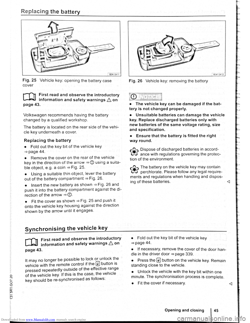
Fig. 25 Vehicle key: opening the battery case
cover
r-f""n First read and observe the introductory
L-kJJ information and safety warnings & on
page 43.
Volkswagen recommends having the battery
changed by a qualified workshop.
The battery is located on the rear side of the vehi
cle ke y underneath a cover.
Replacing the battery
• Fold out the key bit of the vehicle key
=>page 44.
• Remove the cover on the rear of the vehicle
key in the direction of t h e a rrow =>CD using a su ita
ble object, e .g . a coin =>Fig . 25.
• Using a suitable th in object, lever the battery
out of the battery compartment =>F ig . 26.
• Insert the new battery as shown =>F ig . 26 and
push it into the battery compartment against the di
rection of the arrow =>CD.
•
Fit the cover as shown =>F ig . 25 and push it
onto the vehicle key housing against the d irect ion
shown by the arrow until it engages.
Synchronising the vehicle key
r-f11 First read and observe the i~troductory
~ information and safety warnmgs 6 on
page 43.
lt may no longer be possible to lock or unlock t~e
vehicle with the remote control if the @ button ts
pressed repeatedly outside of the effective r~nge
of the vehicle key. If this is the case, the vehtcle
key should be re-synchronised as follows:
851"·0412
Fig. 26 Vehicle key: removing the battery
• The vehicle key can be damaged if the bat
tery is not changed properly.
• Unsuitable batteries can damage the vehicle
key. Replace discharged batteries only with
new batteries of the same voltage rating, size
and specif ication.
• Ensure that the battery is fitted the right
way round.
~ Dispo se of discharged batteries in accord
~ ance with regulations governing the protec
tion
of the enviro nment.
~ The battery on the vehicle key may contain
~ perchlorate . Please follow any legal require
ments and regulations when handling and dispos-
ing
of these batteries.
=>page 44.
• If necessary, remove the cover of the door han
dle in the driver door =>page 339.
• Press the @ button on the vehicle key. Remain
standing close to the vehicle .
• Unlock the vehicle w ith the key bit within one
minute. The synchronisation process is complete.
• Fit the cover if necessary.
Page 50 of 138
Downloaded from www.Manualslib.com manuals search engine Electrical controls on the front seats ~~~~~~~~~~~~-----------------------
®
651<-()590
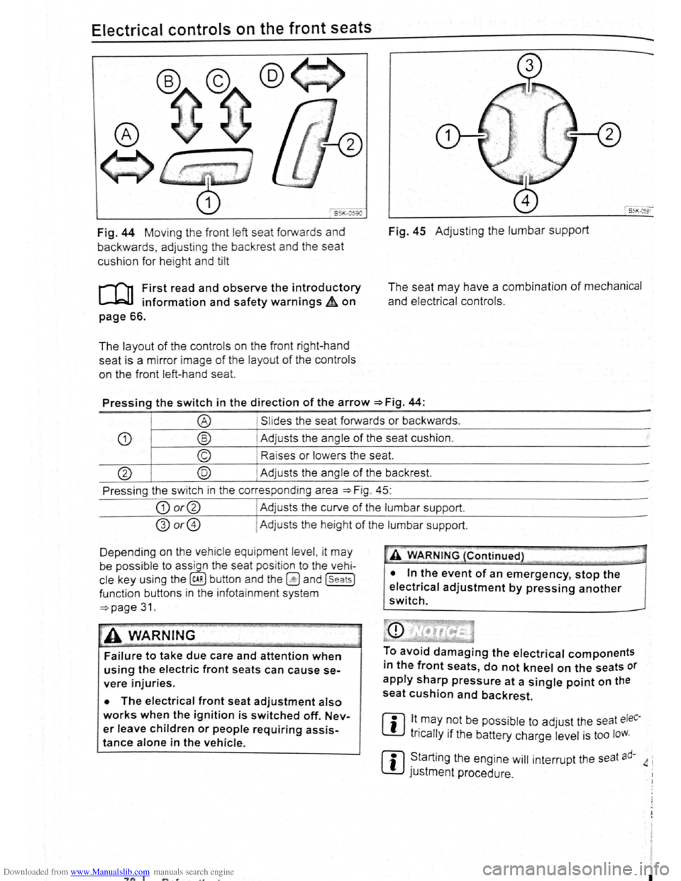
Fig. 44 Moving th e front left seat forwards and
backwards , ad j
usting the backrest and the seat
cushion for hei
ght and tilt
r-('n First read and observe the introductory
L-.lc:J.I information and safety warnings~ on
page 66.
The layout of the contro ls on the front r ight-hand
seat is a m irror image
of the layout of th e contro ls
on the front left-hand sea
t.
Fig. 45 Adju stin g the lumbar support
The seat may have a combination of mechanical
and electrical controls.
Pressing the switch in the direction of the arrow ~Fig. 44:
® Slides the seat forwards or backwards .
CD ® Adjusts the ang le of the seat cushion.
© Raises or lower s the seat.
@ @ Adjust s th e angle of the backrest.
Press ing the s witch in th e corresponding area
~Fig. 45:
CD or@ I Adjusts the curv e of the lumbar support.
@or@ I Ad justs the he ight of the lumbar support .
D epending on the veh ic le equ ipment leve l, it
may
be possib le to ass ign the seat pos it ion to the vehi
cle key using the @ill button and the~ and (seats]
funct ion buttons in the info ta inment system
~page 31.
~A WARNING
Failure to take due care and attention when
using the electric front seats can cause se
vere injuries.
• The electrical front seat adjustment also
works when the ignition is switched off. Nev
er leave children or people requiring assis
tance alone in the vehicle.
~"'A WARNING (Continued} --~ ~ -·-
• In the event of an emergency, stop the
electrical adjustment by pressing another
switch.
To avoid damaging the electrical components
in the front seats, do not kneel on the seats or
apply sharp pressure at a single point on the
seat cushion and backrest.
m lt.may ~Ot be poss ib le to adjust the seat eleC·
W tncally 1f the battery charge level is too loW.
m ~tarting the engine will interrupt the seat ad· 4 i
W JUStment procedure .
"7n I I
Page 52 of 138
Downloaded from www.Manualslib.com manuals search engine ~emoving and fitting head restraints
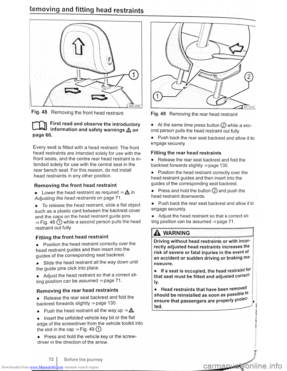
Fig. 48 Removing the front head restraint
r-f'n First read and observe the introductory
L-lcJJ information and safety warnings & on
page 66.
Every seat is fitted with a head restraint. The front
head restraints are intended solely for use with the
front seats, and the centre rear head restra int is in
tended solely for use with the central seat in the
rear bench seat. For this reason , do not install
head restraints in any other position.
Removing the front head restraint
• Lower the head restraint as required ===> & in
Adjusting the head restraints on page 71.
• To release the head restraint , slide a flat object
such as a plas tic card between the backrest cover
and the caps on the head restraint guide pins
===>Fig. 48 G) while a second person pulls the head
restraint
out fully .
Fitting the front head restraint
• Position the head restraint correctly over the
head restraint guides and then insert into the
guides of the corresponding seat backrest.
• Slide the head restraint all the way down until
the guide pins click into place .
• Adjust the head restraint so that a correct sit
ting position can be assumed
===>page 71.
Removing the rear head restraints
• Release the rear seat backrest and fold the
backrest forwards slightly
===>page 130.
• Push
the head restraint all the way up ===> &.
• Insert the unfolded vehicle key bit or the flat
edge
of the screwdriver from the vehicle tool kit into
the slot in the cap
===>Fig. 49 G).
• Press and hold the vehicle key or the screw
driver in the direction
of the arrow .
Before the journey
Fig. 49 Removing the rear head restraint
• At the same time press button @ while a sec
ond person
pulls the head restraint out fully .
• Push back the rear seat backrest and allow it to
engage securely .
Fitting the rear head restraints
• Release the rear seat backrest and fold the
backrest forwards slightly
===>page 130.
• Position
the head restraint correctly over the
head restraint guides and then insert into the
guides
of the corresponding seat backrest.
• Press and hold the button @and push the
head restraint downwards .
• Push back the rear seat backrest and allow it to
engage securely.
• Adjust the head restraint so that a correct sit
ting position can be assumed ===>page 71.
A WARNING .
Driving without head restraints or with incor·
rectly adjusted head restraints increases the
risk of severe or fatal injuries in the event of
an
accident or sudden driving or braking ma·
noeuvre.
• If a seat is occupied, the head restraint tor
that seat must be fitted and adjusted correct·
ly.
•
Head restraints that have been removed
should be reinstalled as soon as possible to
tee· ensure that passengers are properly pro ~
~ ted.
) )
.
~ . ,
Page 72 of 138

Downloaded from www.Manualslib.com manuals search engine . -~~~Q§@~~iC!~;a--................................................................ ~~~~--~--~~~~.a.-.. __ .... ~.c .. ~~~~ ~ .. ~h:;;;;;;..,-~= I n 70 a M= ,..._ ~;e,--~· ... - - -v· --.. iiA.ir ...
...
Stowage compartment on the driver side
Fig. 109 On the driver side: stowage compart
ment
To open, press the button ~Fig. 109 G) dow .
pull the grip in the direction of the arrow. n ana
To close, press the cover upwards until it e ngages
ffi A coin holder may be located on the inside of W the cover.
Stowage compartment in the roof console (glasses compartment)
Fig. 110 In the roof console : stowage compart
ment
r-('n First read and observe the introductory
~ information and safety warnings A on
page 151.
The stowage compartment can be used for storing
glasses or other objects.
To open, press and release the button ~Fig. 110
(arrow).
To close, press the cover upwards until it engages <
Stowage compartment in the front centre console _____.
Fig. 111 In the centre console: stowage compart
ment
1521
-----
B efore the journey
. troductorY
[Q] First read and observe the 1~ 5 & on . f ty warnm9 • information and sa e
page151.
f the stowage To open, briefly press the cover 0
compartment ~Fig. 111 (arrow). ver
artment eo To close, push the stowage comp
down as far as it will go. ·n tne • -y conta1 1 ?
rn
The stowage compartment m a AUX-IN . ( ~ th8 ' t factory -fitted USB socket ' Mr:DIA-IN) , • · ket ( ~ tefl'l· E socket '"'' or the multimedia soc ·g a tion s Y5
, •
~ Booklet Radio or ~Booklet N avt • ~
Page 75 of 138
Downloaded from www.Manualslib.com manuals search engine CD
Please note the following to help avoid damag o
and premature wear:
• Do not rest your hand on the g ear le ve r
when
driving. The pressure from your hand is
passed onto the selector forks in the gearbox.
Automatic gearbox: selecting a gear
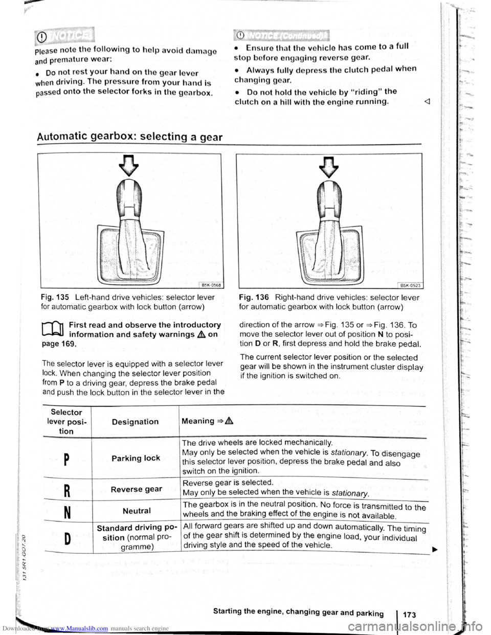
Fig . 135 Left-hand drive vehicles : selector lever
for automatic gearbox with lock button (arrow)
r-('n First read and observe the introductory
~ information and safety warnings & on
page 169.
The selector lever is equipped with a selector lever
lock .
When changing the selector lever position
from P to a driving gear, depress the brake pedal
and push the lock button in the selector lever in the
Selector
lever posi-Designation Meaning ~ .&.
tion
stop bofore engaging re verse gear.
• Always fully d epress the clutch pedal when
changing gear.
• Do not hold the vehicle by "riding" the
clutch on a hill with the engine running.
Fig. 136 Right-hand drive vehicles : selector lever
for automatic gearbox with lock button (arrow)
direction
of the arrow ~Fig. 135 or ~Fig. 136. To
move the selector
lever out of position N to posi
tion D
or R, first depress and hold the brake pedal.
The current selector lever position or the selected
gear
will be shown in the instrument cluster display
if the ignition is switched on.
The drive wheels are locked mechanically .
p Parking lock May only be selected ~hen the vehicle is stationary. To disengage
this selector lever pos1t1on, depress the brake pedal and also
switch on the ignition .
R Reverse gear Reverse gear is selected.
May only be selected when the vehicle is
stationary.
N Neutral The gearbox is in the neutral position . No force is transmitted to the
wheels and the braking effect
of the engine is not available .
Standard driving po-All forward ge~r~ are shift~d up and down automatically . The timing
D sition (normal pro-of the gear sh1ft 1s determmed by the engine load, your individual
gramme) driving
style and the speed
of the vehicle . -
Starting the engine, changing gear and parking 173
Page 94 of 138
Downloaded from www.Manualslib.com manuals search engine ~ ; ) J
Reverse assist system (Rear Assist)
eo Introduction
ThiS c hflp t r co nlc:tln s Informa tio n on th e fo llowing
subjor.ts :
G 11 rat Infor m ation . . . . . . . . . . . . . . . . . . . . . . 210
Parking ....... ········· ....... . ........ 2 12
A cam era in th e ta il g a te he lp s th e driver when re
ve rsing o r m an o e uv ring the ve hi cle . The came ra
picture and th e o rienta tio n lin e s projecte d by the
syste m are di sp la ye d o n the s creen of th e facto ry
littcd ra d io or n avi gatio n sy ste m .
Additional information and warnings:
• Exte rio r v ie ws ~p age 6
• Accessories, modifica tio ns , re pai rs a nd re ne w al
of parts ::>p ag e 32 0
•
=>Bookle t R ad io o r ~Booklet N av iga tio n sy s
te m
A WARNING
Using cameras to estimate the distance from
obstacles (persons, vehicle etc. ) is inaccurate
and can cause accidents and severe injuries.
• The camera lens enlarges and distorts the
field of vision and makes objects on the
screen appear to be different and imprecise.
• Certain objects, for example narrow posts
or grids , may be difficult or impossible to see
on the screen because of its low resolution or
poor light conditions.
• The camera has blind spots within which
obstacles and people cannot be detected.
• Keep the camera lens clean, free of snow
and ice and do not cover it.
A WARNING
~------------~--------~~~------~ The technology of the Rear Assist system
cannot overcome the laws of physics or sys
tem-related vehicle limitations. Careless or
unintentional use of the Rear Assist system
can cause accidents and severe injuries. The
system is not a substitute for the full concen
tration of the driver.
• Adapt your speed and driving style to suit
visibility, weather, road and traffic conditions.
• Keep looking to check the direction in
which you are parking and the relevant area
around the vehicle. The front of the vehicle
swings out more than the rear of the vehicle.
•
Do not allow the images shown on the
screen to distract you from the traffic around
you.
• Always monitor the area around the vehi
cle as the cameras will not always detect in
fants, animals and objects.
• The system may not be able to d isplay all
areas clearly.
• The Rear Assist system should only be
used when the tailgate is fully closed.
• The camera only shows two-dimensional
images on the screen. The lack of depth of field
means that recesses and protruding objects on
the ground may only be detected with difficulty,
or may not be detected at all.
• The camera may not always be able to de
tect objects such as thin rails, fences, posts,
trees etc. This can result in damage to your ve
hicle.
Driver assist systems 209
Page 136 of 138
Downloaded from www.Manualslib.com manuals search engine First aid kit, warning triangle and fire extinguisher
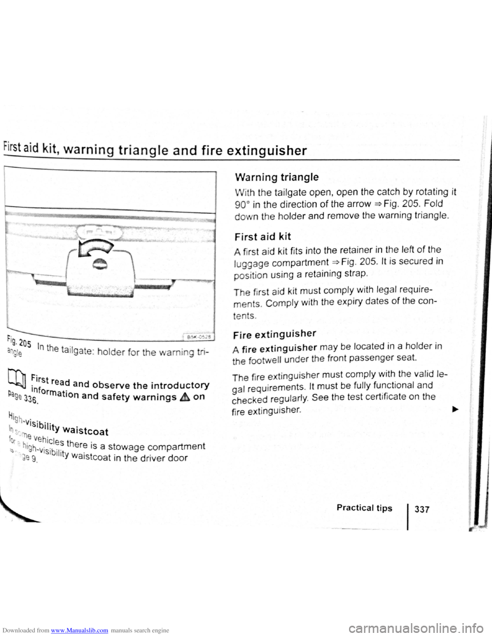
r-~-~-~3
rig , 205
an g le In the ta ilgate : holder for the warning tri-
N'l, First re d L..bJJ ·1nf a and observe the introductory p orrn r age 33s. a IOn and safety warnings & on
H· '9h -visib· .
In ~-"r) '11ty Waistcoat
fot .e Vehicles th .
~ hlgh~visibl er~ 1s a stowage compartment
~e 9. 11ty Waistcoat in the driver door
Warning triangle
With the tailgate open, open the catch by rotat ing it
90° in the direction of the arrow =>F ig . 205 . Fold
down the holder and remove the warning triangle.
First aid kit
A first aid k it fits into the retainer in the left of the
luggage compartment =>Fig . 205 . lt is secured in
positio n using a reta ining strap .
The first aid k it must comply with legal require
ments. Comply with the expiry dates of the con-
tents .
Fire extinguisher
A fire extinguisher may be located in a holder i n
the tootwell under the front passenger seat.
T he fir e ext inguisher
must comply with the valid le
gal requirements . lt must be fully functional and
c h ecked regul
arly . See the test certificate on the
fire e
xtinguisher . ~
Practical tips 1337