Page 388 of 538

386 4-3. Do-it-yourself maintenance
■When to replace your vehicle’s tires
Tires should be replaced if:
●You have tire damage such as cuts, splits, cracks deep enough to
expose the fabric or bulges indicating internal damage
●A tire goes flat repeatedly or cannot be properly repaired due to the
size or location of a cut or other damage
If you are not sure, consult with your Toyota dealer.
■Replacing tires and wheels
If the ID code of the tire pressure warning valve and transmitter is not
registered, the tire pre ssure warning system will not work properly. After
driving for about 20 minutes, the ti re pressure warning light comes on
after blinking for 1 minute to indicate a system malfunction.
■Tire life
Any tire over 6 years old must be checked by a qualified technician even
if they have seldom or never been used or damage is not obvious.
■If the tread wears down below 0.16 in. (4 mm) on snow tires
The effectiveness of snow tires is lost.
■If you push the tire pressure warning reset switch accidentally
If initialization is performed, adjust the tire in flation pressure to the speci-
fied level and initialize the tire pressure warning system again.
Page 389 of 538

387
4-3. Do-it-yourself maintenance
4
Maintenance and care
■When the initialization of the tire pressure warning system has
failed
Initialization can be completed in a few minutes. However, in the follow-
ing cases, the settings has not bee
n recorded and the system will not
operate properly. If repeated attempts to record tire inflation pressure
settings are unsuccessful, have the vehicle inspected by your Toyota
dealer.
●When operating the tire pressure warning reset switch, the tire pres-
sure warning light does not flash 3 times.
●After carrying out the initialization procedure, the tire pressure warn-
ing light blinks for 1 minute then stays on after driving for about 20
minutes.
■Routine tire inflation pressure checks
The tire pressure warning system doe s not replace routine tire inflation
pressure checks. Make su re to check tire inflation pressure as part of
your routine of daily vehicle checks.
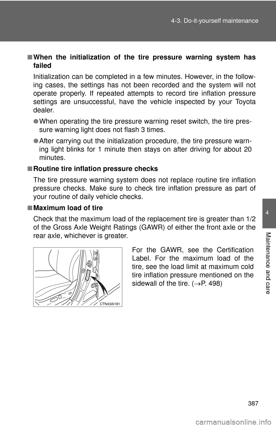
■Maximum load of tire
Check that the maximum load of the replacement tire is greater than 1/2
of the Gross Axle Weight Ratings (GAW R) of either the front axle or the
rear axle, whichever is greater.
For the GAWR, see the Certification
Label. For the maximum load of the
tire, see the load limit at maximum cold
tire inflation pressure mentioned on the
sidewall of the tire. ( P. 498)
Page 392 of 538

390 4-3. Do-it-yourself maintenance
CAUTION
■When inspecting or replacing tires
Observe the following precautions to prevent accidents.
Failure to do so may cause damage to parts of the drive train, as well as
dangerous handling characteristics, which may lead to an accident
resulting in death or serious injury.
●Do not mix tires of different makes, models or tread patterns.
Also, do not mix tires of remarkably different treadwear.
●Do not use tire sizes other than those recommended by Toyota.
●Do not mix differently constructed ti res (radial, bias-belted or bias-ply
tires).
●Do not mix summer, all season and winter tires.
■When initializing the tire pressure warning system
Do not press the tire pressure warnin g reset switch without first adjusting
the tire inflation pressure to the spec ified level. Otherwise, the tire pres-
sure warning light may not come on ev en if the tire inflation pressure is
low, or it may come on when the tire inflation pressure is actually normal.
Page 411 of 538

409
4-3. Do-it-yourself maintenance
4
Maintenance and care
14 RR FOG
10 A No circuit
15 ST/AM2 30 AStarting system, GAUGE NO.2,
IGN, INJ
16 ALT 120 ARR FOG, FR DEF, HTR, ABS
NO.1, ABS NO.2, RR DEF, RR
PWR SEAT, H-LP CLN, CDS FAN,
RDI FAN, MSB, TAIL, PANEL, FR
FOG, CIG, RADIO No.2, ECU-
ACC, PWR OUTLET, GAUGE
No.1, ECU IG No.1, ECU IG No.2,
H-LP LVL, WASH, A/C No.2, S-
HTR, WIP, P/SEAT, DOOR No.2,
POWER, RR DOOR LH, RR
DOOR RH, ECU-B No.2, OBD,
FUEL OPN, PWR, STOP, S/ROOF,
TI&TE, A/C, AM1
17 STR LOCK 20 A Steering lock system
18 IG2 20 AMultiport fuel injection system/
sequential multiport fuel injection
system, starting system, GAUGE
NO.2, IGN, INJ
19 HAZ 15 ATurn signal lights, gauge and
meters
20 ETCS 10 AMultiport fuel injection system/
sequential multiport fuel injection
system
21 EFI2 30 AMultiport fuel injection system/
sequential multiport fuel injection
system
22 MAYDAY/TEL 7.5 A No circuit
23 ALT-S 7.5 A Charging system
24 AM2 7.5 A Main body ECU
FuseAmpereCircuit
Page 412 of 538

410 4-3. Do-it-yourself maintenance
25 EFI MAIN 30 AMultiport fuel injection system/
sequential multiport fuel injection
system, EFI NO.2, EFI NO.3, main
body ECU
26 AMP 25 A Audio system
27 DOOR NO.1 25 A Main body ECU
28 RADIO NO.1 15 A Audio system, navigation system
29 ECU-B NO.1 10 A Wireless remote control system,
front passenger occupant classifi-
cation system, main body ECU
30 DOME 10 AGauges and meters, trunk light,
engine switch light, door courtesy
lights, interior light, personal lights,
clock, smart key system
31 H-LP(LH) 15 A Left-hand headlight (high beam)
32 H-LP(RH) 15 A Right-hand headlight (high beam)
33 H-LP(LL) 15 A Left-hand headlight (low beam)
34 H-LP(RL) 15 A Right-hand headlight (low beam)
35 HORN 10 A Horns
36 EFI NO.1 10 ASmart key system, multiport fuel
injection system/sequential multi-
port fuel injection system, main
body ECU
37 MPX-B 10 A Gauges and meters
38 A/F 20 A No circuit
39 S-HORN 7.5 A Horns
40 EFI NO.2 15 AMultiport fuel injection system/
sequential multiport fuel injection
system
41 EFI NO.3 10 AMultiport fuel injection system/
sequential multiport fuel injection
system
FuseAmpereCircuit
Page 414 of 538

412 4-3. Do-it-yourself maintenance
14 ALT120 ARR FOG, FR DEF, HTR, ABS
NO.1, FAN MAIN, ABS NO.2, RR
DEF, RR PWR SEAT, H- LP CLN,
CDS FAN, RDI FAN, MSB, TAIL,
PANEL, FR FOG, CIG, RADIO
No.2, ECU-ACC, PWR OUTLET,
GAUGE No.1, ECU IG No.1, ECU
IG No.2, H-LP LVL, WASH, A/C
No.2, S-HTR, WIP, P/SEAT, DOOR
No.2, POWER, RR DOOR LH, RR
DOOR RH, ECU-B No.2, OBD,
FUEL OPN, PWR, STOP, S/ROOF,
TI&TE, A/C, AM1
15 STR LOCK 20 A Steering lock system
16 IG2 20 AMultiport fuel injection system/
sequential multiport fuel injection
system, starting system, GAUGE
NO.2, IGN, INJ
17 HAZ 15 ATurn signal lights, gauge and
meters
18 ETCS 10 AMultiport fuel injection system/
sequential multiport fuel injection
system
19 E-ACM 10 A No circuit
20 MAYDAY/TEL 7.5 A No circuit
21 ALT-S 7.5 A Charging system
22 AM2 7.5 A Main body ECU
23 EFI MAIN 30 AMultiport fuel injection system/
sequential multiport fuel injection
system, EFI NO.2, EFI NO.3
24 AMP 25 A Audio system
25 DOOR NO.1 25 A Main body ECU
26 RADIO NO.1 15 A Audio system, navigation system
FuseAmpereCircuit
Page 415 of 538

413
4-3. Do-it-yourself maintenance
4
Maintenance and care
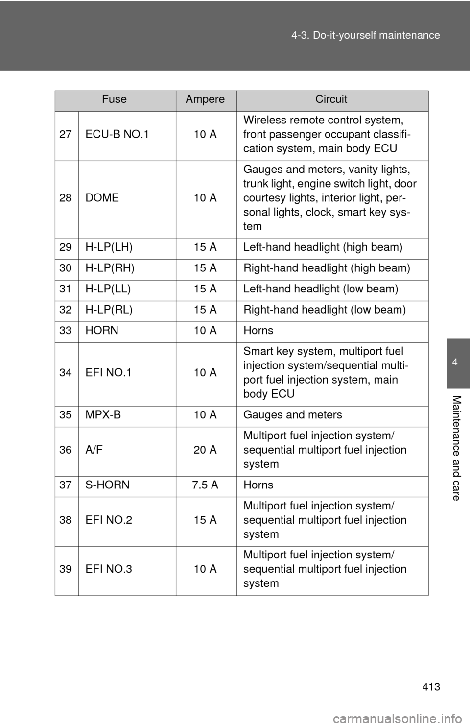
27 ECU-B NO.1 10 A
Wireless remote control system,
front passenger occupant classifi-
cation system, main body ECU
28 DOME 10 A Gauges and meters, vanity lights,
trunk light, engine switch light, door
courtesy lights, interior light, per-
sonal lights, clock, smart key sys-
tem
29 H-LP(LH) 15 A Left-hand headlight (high beam)
30 H-LP(RH) 15 A Right-hand headlight (high beam)
31 H-LP(LL) 15 A Left-hand headlight (low beam)
32 H-LP(RL) 15 A Right-hand headlight (low beam)
33 HORN 10 A Horns
34 EFI NO.1 10 A Smart key system, multiport fuel
injection system/sequential multi-
port fuel injection system, main
body ECU
35 MPX-B 10 A Gauges and meters
36 A/F 20 A Multiport fuel injection system/
sequential multiport fuel injection
system
37 S-HORN 7.5 A Horns
38 EFI NO.2 15 A Multiport fuel injection system/
sequential multiport fuel injection
system
39 EFI NO.3 10 A Multiport fuel injection system/
sequential multiport fuel injection
system
FuseAmpereCircuit
Page 416 of 538
414 4-3. Do-it-yourself maintenance
■Under the instrument panel
FuseAmpereCircuit
1 RR DOOR RH 25 A Rear right power window
2 RR DOOR LH 25 A Rear left power window
3 FUEL OPN 7.5 A No circuit
4 FR FOG 15 A Front fog lights
5 OBD 7.5 A On-board diagnosis system
6 ECU-B NO.2 7.5 A Power windows
7 STOP 10 A High mounted stoplight, shift lock
control system, multiport fuel injec-
tion system/sequential multiport
fuel injection system, main body
ECU, anti-lock brake system, vehi-
cle stability control system, traction
control system, brake assist sys-
tem
8 TI&TE 30 A No circuit
9 AM1 7.5 A Multiport fuel injection system/
sequential multiport fuel injection
system
10 A/C 7.5 A Air conditioning system