Page 186 of 297

5-45OTHER CONTROLS AND EQUIPMENT
80J23-03E
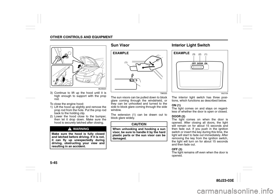
80JS024
3) Continue to lift up the hood until it is
high enough to support with the prop
rod.
To close the engine hood:
1) Lift the hood up slightly and remove the
prop rod from the hole. Put the prop rod
back to the holding clip.
2) Lower the hood close to the bumper,
then let it drop down. Make sure the
hood is securely latched after closing.
Sun Visor
79K055
The sun visors can be pulled down to block
glare coming through the windshield, or
they can be unhooked and turned to the
side to block glare coming through the side
window.
The extension (1) can be drawn out to
block glare widely.
Interior Light Switch
64J104
The interior light switch has three posi-
tions, which functions as described below.
ON (1)
The light comes on and stays on regard-
less of whether the door is open or closed.
DOOR (2)
The light comes on when the door is
opened. After closing all doors, the light
will remain on for about 15 seconds and
then fade out. If you push in the ignition
switch or insert the key during this time, the
light will start to fade out immediately. After
removing the key from the ignition switch,
the light will turn on for about 15 seconds
and then fade out.
OFF (3)
The light remains off even when the door is
opened.
WARNING
Make sure the hood is fully closed
and latched before driving. If it is not,
it can fly up unexpectedly during
driving, obstructing your view and
resulting in an accident.
CAUTION
When unhooking and hooking a sun
visor, be sure to handle it by the hard
plastic parts or the sun visor can be
damaged.
(1)
EXAMPLE
(1)
(2)
(3)
EXAMPLE
Page 237 of 297

7-32
INSPECTION AND MAINTENANCE
80J23-03E
Snow Tires
Your vehicle is equipped with all-sea-
son tires which are designed for use in
summer and most winter conditions.
For improved traction in severe winter
conditions, SUZUKI recommends
mounting radial snow tires on all four
wheels. Snow tires must be the same
size as the standard tires. Also be sure
to use the tires of the same type and
brand on all four wheels of your vehi-
cle.GLOSSARY OF TIRE TERMINOL-
OGY
Accessory Weight – the combined
weight (in excess of those standard
items which may be replaced) of CVT,
power steering, power brakes, power
windows, power seats, radio, and
heater, to the extent that these items
are available as factory-installed
equipment (whether installed or not).
Cold Tire Inflation Pressure – the pres-
sure in a tire that has been driven less
than 1 mile or has been standing for
three hours or more.
Curb Weight – the weight of a motor
vehicle with standard equipment
including the maximum capacity of
fuel, oil, and coolant, and, if so
equipped, air conditioning and addi-
tional weight optional engine.
Intended Outboard Sidewall – (1) the
sidewall that contains a whitewall,
bears white lettering or bears manu-
facturer, brand, and/or model name
molding that is higher or deeper than
the same molding on the other side-
wall of the tire, or (2) the outward fac-
ing sidewall of an asymmetrical tire
that has a particular side that must
always face outward when mounted
on a vehicle.Maximum Inflation Pressure – the max-
imum cold inflation pressure a tire is
designed to support in normal service.
Maximum Loaded Vehicle Weight –
the sum of curb weight, accessory
weight, vehicle capacity weight (total
load capacity), and production options
weight.
Normal Occupant Weight – 68 kilo-
grams times the number of occupants
specified in the second column of
Table 1 (shown below).
Occupant distribution – distribution of
occupants in a vehicle as specified in
the third column of Table 1 (shown
below).
Production Options Weight – the com-
bined weight of those installed regular
production options weighing over 2.3
kilograms in excess of those standard
items which they replace, not previ-
ously considered in curb weight or
accessory weight, including heavy
duty brakes, ride levelers, roof rack,
heavy duty battery, and special trim.
Recommended Inflation Pressure –
the cold tire inflation pressure recom-
mended by a manufacturer.
Rim – metal support for a tire or tire
and tube assembly upon which the tire
beads are seated.
Page 242 of 297

7-37INSPECTION AND MAINTENANCE
80J23-03E
The main fuse, primary fuses and some of
the individual fuses are located in the
engine compartment. If the main fuse
blows, no electrical component will func-
tion. If a primary fuse blows, no electrical
component in the corresponding load
group will function. When replacing the
main fuse, a primary fuse or an individual
fuse, use a genuine SUZUKI replacement.
To remove a fuse, use the fuse puller pro-
vided in the fuse box. The amperage of
each fuse is shown in the back of the fuse
box cover.
60A243
NOTE:
Make sure that the fuse box always carries
spare fuses. MAIN FUSE / PRIMARY FUSE
(1) 80A All electric load
(2) 50APower window, Ignition,
Wiper, Starter
(3) 50ATail light, Rear defogger,
Door lock, Hazard/Horn,
Dome
(4) – Blank
(5) – Blank
(6) 15A Head light (Right) fuse
(7) 15A Head light (Left) fuse
(8) 20A Front fog light fuse
(9) – Blank
(10) 40A ABS motor fuse
(11) 30A Radiator fan fuse
(12) 30A ABS solenoid fuse
(13) 30A Starting motor fuse
(14) 50A Ignition switch fuse
(15) 30A Blower fan fuse
(16) 20A Air compressor fuse
(17) 15A Throttle motor fuse
(18) 15A Automatic transaxle fuse
(19) 15A Fuel injection fuse
(20) – Automatic transaxle relay
(21) – Air compressor relay
(22) – Fuel pump relay
(23) – Condenser fan relay
(24) – Front fog light relay
(25) – Throttle motor relay
(26) – FI MAIN relay
(27) – Starting motor relay
(28) – Radiator fan relay
(29) – Radiator fan relay 2
(30) – Radiator fan relay 3
WARNING
If the main fuse or a primary fuse
blows, be sure to have your vehicle
inspected by an authorized SUZUKI
dealer. Always use a genuine SUZUKI
replacement. Never use a substitute
such as a wire even for a temporary
fix, or extensive electrical damage
and a fire can result.
BLOWNOK
Page 243 of 297
7-38
INSPECTION AND MAINTENANCE
80J23-03E
Fuses under the Dash Board
79J093
SX4
80J053
SX4 SEDAN
80JC003
(1) (2) (3) (4) (5) (6)
(8) (9) (10) (11) (12) (13) (14) (15) (16)
(18) (17) (19) (20) (21) (22) (23)(7)
MAIN FUSE / PRIMARY FUSE
(1) 15A Rear wiper
(2) 15A Ignition coil
(3) 10A Back-up light
(4) 10A Meter
(5) 15A Accessory
(6) 15A Accessory 2
(7) 30A Power window
(8) 30A Wiper
(9) 10A IG1 SIG
(10) 15A Air bag
(11) 10A Anti-lock brake system
(12) 15A 4WD
(13) 10A Stop light
(14) 20A Door lock
(15) 10A Rear fog light
(16) 10A ST SIG
(17) 15A Seat heater
(18) 10A IG 2 SIG
(19) 10A Tail light
(20) 15A Dome
(21) 30A Rear defogger
(22) 15A Horn / Hazard
(23) – Blank
MAIN FUSE / PRIMARY FUSE
(1) 15A Rear wiper
(2) 15A Ignition coil
(3) 10A Back-up light
(4) 10A Meter
(5) 15A Accessory
(6) 15A Accessory 2
(7) 30A Power window
(1) (2) (3) (4) (5) (6)
(8) (9) (10) (11) (12) (13)
(21)
(24)
(14) (15) (16)
(18) (17) (19) (20) (22) (23)(7)
Page 251 of 297
7-46
INSPECTION AND MAINTENANCE
80J23-03E
80JM076
3) Pushing the unguiform prongs (3)
toward inside and remove the bulb
holder (4).
4) Replace the bulbs.
To install a high-mounted stop light
housing in the reverse order of removal.SX4 SEDAN
80JM132
To remove the high-mounted stop light
housing, pinch both side of the clip (1) and
push it in.
Wiper Blades
80G083
If the wiper blades become brittle or dam-
aged, or make streaks when wiping,
replace the wiper blades.
To install new wiper blades, follow the pro-
cedures below.
NOTE:
Some wiper blades may be different from
the ones described here depending on
vehicle specifications. If so, consult your
SUZUKI dealer for proper replacement
method.
(3) (3)
(4)
(1)
CAUTION
To avoid scratching or breaking the
window, do not let the wiper arm
strike the window while replacing the
wiper blade.
Page 253 of 297
7-48
INSPECTION AND MAINTENANCE
80J23-03E
52D124
(3) Retainer
4) If the new blade is provided without the
two metal retainers, move them from
the old blade to the new one.Installation
52D125
(4) Locked end
5) Install the new blade in the reverse
order of removal, with the locked end
positioned toward the wiper arm. Make
sure the blade is properly retained by
all the hooks. Grasp the blade near the
locked end and pull in the direction of
the arrows to lock the end into place.
6) Reinstall wiper frame to arm, making
sure that the lock lever is snapped
securely into the arm.To remove some types of rear wiper
frame from the wiper arm:
1) Hold the arm away from the window.
80G146
2) Remove the wiper frame from the arm
as shown.
Page 279 of 297
11-1
FUSES AND PROTECTED CIRCUITS
80J23-03E
11
FUSES AND PROTECTED CIRCUITS
80J101
COLOR/SIZE (AMPS)
PROTECTED CIRCUIT
In engine
compartment MAIN
FUSE
BOX(1) BLACK (80) All electric load
(2) RED (50) Power window, Ignition, Wiper, Starter
(3) RED (50) Tail light, Rear defogger, Door lock, Hazard/Horn, Dome
(4) – Blank
(5) – Blank
(6) BLUE (15) Head light (Right) fuse
(7) BLUE (15) Head light (Left) fuse
(8) YELLOW (20) Front fog light fuse
(9) – Blank
(10) GREEN (40) ABS motor fuse
(1)
(2) (3)
(28) (27) (26) (25) (6) (7) (9) (11)
(15) (16) (17) (18) (19)
(24)
(8) (4) (5) (10)
(22) (21)
(23)(20)(12) (13) (14)
(30)
(29)
Fuses and Protected Circuits: 7
Page 282 of 297
11-4FUSES AND PROTECTED CIRCUITS
80J23-03E
SX4
80J053
COLOR/SIZE (AMPS)
FUSE NAME PROTECTED CIRCUIT
Under the
dashboard FUSE
BOX(1) BLUE (15) RR WIP Rear wiper
(2) BLUE (15) IG COIL Ignition coil
(3) RED (10) BACK Back-up light
(4) RED (10) MTR Meter
(5) BLUE (15) ACC Accessory
(6) BLUE (15) ACC2 Accessory 2
(7) PINK (30) P/W Power window
(8) GREEN (30) WIP Wiper
(9) RED (10) IG1 SIG IG1 SIG
(10) BLUE (15) A/B Air bag
(11) RED (10) ABS Anti-lock brake system
(1) (2) (3) (4) (5) (6)
(8) (9) (10) (11) (12) (13) (14) (15) (16)
(18) (17) (19) (20) (21) (22) (23)(7)
Fuses and Protected Circuits: 7