2010 SUZUKI SX4 turn signal
[x] Cancel search: turn signalPage 95 of 297
2-78
BEFORE DRIVING
80J23-03E
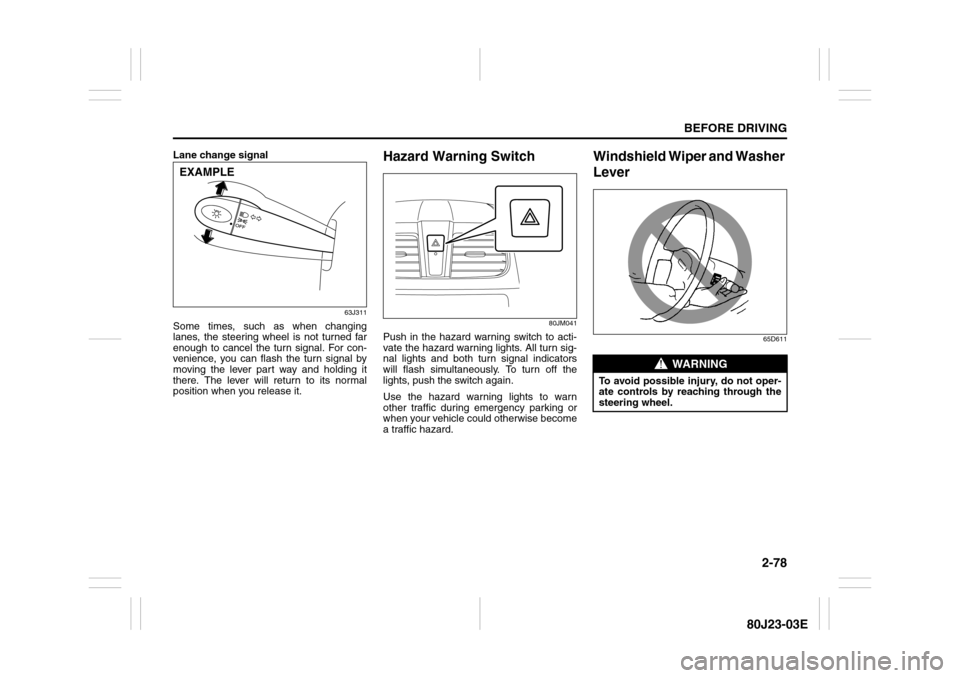
Lane change signal
63J311
Some times, such as when changing
lanes, the steering wheel is not turned far
enough to cancel the turn signal. For con-
venience, you can flash the turn signal by
moving the lever part way and holding it
there. The lever will return to its normal
position when you release it.
Hazard Warning Switch
80JM041
Push in the hazard warning switch to acti-
vate the hazard warning lights. All turn sig-
nal lights and both turn signal indicators
will flash simultaneously. To turn off the
lights, push the switch again.
Use the hazard warning lights to warn
other traffic during emergency parking or
when your vehicle could otherwise become
a traffic hazard.
Windshield Wiper and Washer
Lever
65D611
EXAMPLE
WARNING
To avoid possible injury, do not oper-
ate controls by reaching through the
steering wheel.
Page 102 of 297
3-1OPERATING YOUR VEHICLE
80J23-03E
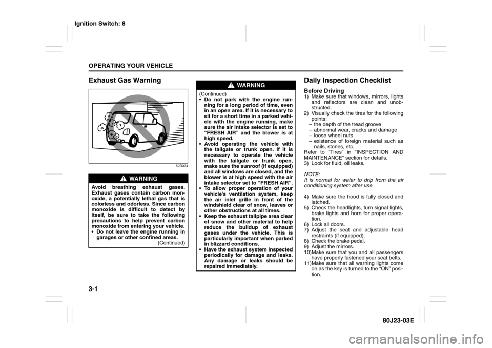
Exhaust Gas Warning
52D334
Daily Inspection ChecklistBefore Driving1) Make sure that windows, mirrors, lights
and reflectors are clean and unob-
structed.
2) Visually check the tires for the following
points:
– the depth of the tread groove
– abnormal wear, cracks and damage
– loose wheel nuts
– existence of foreign material such as
nails, stones, etc.
Refer to “Tires” in “INSPECTION AND
MAINTENANCE” section for details.
3) Look for fluid, oil leaks.
NOTE:
It is normal for water to drip from the air
conditioning system after use.
4) Make sure the hood is fully closed and
latched.
5) Check the headlights, turn signal lights,
brake lights and horn for proper opera-
tion.
6) Lock all doors.
7) Adjust the seat and adjustable head
restraints (if equipped).
8) Check the brake pedal.
9) Adjust the mirrors.
10)Make sure that you and all passengers
have properly fastened your seat belts.
11)Make sure that all warning lights come
on as the key is turned to the “ON” posi-
tion.
WARNING
Avoid breathing exhaust gases.
Exhaust gases contain carbon mon-
oxide, a potentially lethal gas that is
colorless and odorless. Since carbon
monoxide is difficult to detect by
itself, be sure to take the following
precautions to help prevent carbon
monoxide from entering your vehicle.
Do not leave the engine running in
garages or other confined areas.
(Continued)
WARNING
(Continued)
Do not park with the engine run-
ning for a long period of time, even
in an open area. If it is necessary to
sit for a short time in a parked vehi-
cle with the engine running, make
sure the air intake selector is set to
“FRESH AIR” and the blower is at
high speed.
Avoid operating the vehicle with
the tailgate or trunk open. If it is
necessary to operate the vehicle
with the tailgate or trunk open,
make sure the sunroof (if equipped)
and all windows are closed, and the
blower is at high speed with the air
intake selector set to “FRESH AIR”.
To allow proper operation of your
vehicle’s ventilation system, keep
the air inlet grille in front of the
windshield clear of snow, leaves or
other obstructions at all times.
Keep the exhaust tailpipe area clear
of snow and other material to help
reduce the buildup of exhaust
gases under the vehicle. This is
particularly important when parked
in blizzard conditions.
Have the exhaust system inspected
periodically for damage and leaks.
Any damage or leaks should be
repaired immediately.
Ignition Switch: 8
Page 104 of 297
3-3OPERATING YOUR VEHICLE
80J23-03E
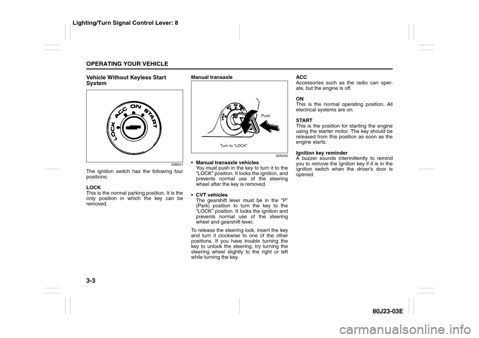
Vehicle Without Keyless Start
System
60B041
The ignition switch has the following four
positions:
LOCK
This is the normal parking position. It is the
only position in which the key can be
removed.Manual transaxle
60A055
Manual transaxle vehicles
You must push in the key to turn it to the
“LOCK” position. It locks the ignition, and
prevents normal use of the steering
wheel after the key is removed.
CVT vehicles
The gearshift lever must be in the “P”
(Park) position to turn the key to the
“LOCK” position. It locks the ignition and
prevents normal use of the steering
wheel and gearshift lever.
To release the steering lock, insert the key
and turn it clockwise to one of the other
positions. If you have trouble turning the
key to unlock the steering, try turning the
steering wheel slightly to the right or left
while turning the key.ACC
Accessories such as the radio can oper-
ate, but the engine is off.
ON
This is the normal operating position. All
electrical systems are on.
START
This is the position for starting the engine
using the starter motor. The key should be
released from this position as soon as the
engine starts.
Ignition key reminder
A buzzer sounds intermittently to remind
you to remove the ignition key if it is in the
ignition switch when the driver’s door is
opened.
Push
Turn to “LOCK”
Lighting/Turn Signal Control Lever: 8
Page 105 of 297
3-4
OPERATING YOUR VEHICLE
80J23-03E
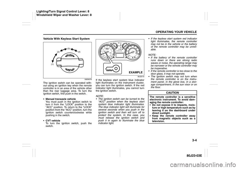
Vehicle With Keyless Start System
56KN076
The ignition switch can be operated with-
out using an ignition key when the remote
controller is in an area of the vehicle other
than the rear luggage area. To turn the
ignition switch, first push in the switch.
Manual transaxle vehicle
You must push in the ignition switch to
turn it from the “LOCK” position to the
“ACC” position. To return to the “LOCK”
position from the “ACC” position, turn the
ignition switch counterclockwise while
pushing in the switch.
CVT vehicle
To turn the ignition switch, push the
switch.
80J2016
If the keyless start system blue indicator
light illuminates on the instrument cluster,
you can turn the ignition switch. If the red
indicator light illuminates, you cannot turn
the ignition switch.
NOTE:
The ignition switch can be turned to the
“ACC” position when the keyless start
system blue indicator light illuminates.
The blue indicator light will illuminate for
several seconds when you push in the
ignition switch and then will turn off to
protect the system. In this case, you
must release the ignition switch and
push it in again to illuminate the blue
indicator light. If the keyless start system red indicator
light illuminates, the remote controller
may not be in the vehicle or the battery
of the remote controller may be unreli-
able.
NOTE:
If the battery of the remote controller
runs down or there are strong radio
waves or noise, the operating range may
be narrower or the remote controller may
be inoperative.
If the remote controller is too close to the
door glass, it may not operate.
The ignition switch may not turn when
the remote controller is on the instru-
ment panel, in the glove box, in a stor-
age compartment, in the sun visor or on
the floor.
(1)(2)(3)
(4)
EXAMPLE
CAUTION
The remote controller is a sensitive
electronic instrument. To avoid dam-
aging the remote controller:
Do not expose it to impacts, mois-
ture or high temperature such as by
leaving it on the dashboard under
direct sunlight.
Keep the remote controller away
from magnetic objects such as a
television.
Lighting/Turn Signal Control Lever: 8
Windshield Wiper and Washer Lever: 8
Page 117 of 297

3-16
OPERATING YOUR VEHICLE
80J23-03E
Using the 2WD/i-AWD
(intelligent All Wheel Drive)
Switch (if equipped)
80J009
This i-AWD system enables you to select
the driving mode according to the driving
conditions by operating the 2WD/i-AWD
switch. With this feature, you can select 3
mode positions, “2WD”, “i-AWD AUTO”
and “i-AWD LOCK” by operating the 2WD/
i-AWD switch even when the vehicle is
moving, provided the front wheels are in
the straight ahead position.Description of 3 Mode 4 x 4 System
Positions2WD
In this position, engine power is supplied to
the front axle only. Use this position for
normal driving (on dry, hard surfaces).i-AWD AUTO
In this position, engine power is supplied to
the front and rear axles at normal speed,
providing greater traction than 2-wheel
drive. Use this position for driving on paved
roads or on slippery roads (icy, snow-cov-
ered, muddy, etc.).
In the AUTO mode, the i-AWD controller
judges the driving conditions using signals
from sensors.
When slipping of the front wheels is
detected, the electronically controlled cou-
pling supplies optimum driving force to the
rear wheels. This function improves driving
stability and running through performance
on rough roads and stabilizes driving per-
formance even on a snow covered up-hill
road or the like.
Also, during normal driving on paved
roads, torque distribution to the rear
wheels is reduced to achieve the nearly
front wheel drive condition, thereby fuel
consumption is improved.
i-AWD LOCK
In this position, engine power is supplied to
the front and rear axles at reduced speed.
Use this position when it is hard to start off
in the “i-AWD AUTO” mode such as in
mud, sand or on snow.
NOTE:
Avoid operating your vehicle in the “i-
AWD LOCK” on wet pavement as much
as possible. Operating your vehicle in
the “i-AWD LOCK” on wet pavementmay cause severe damage to the drive
train.
As the vehicle speed increases, the “i-
AWD LOCK” mode is automatically can-
celed and the “i-AWD AUTO” mode is
selected.
When the ignition switch is turned to the
“OFF” position, the “i-AWD LOCK” mode
is canceled.
2WD/i-AWD Switch OperationOperate the 2WD/i-AWD switch according
to the appropriate procedure described
below:
How to turn on 2WD/i-AWD switch
2WD/i-AWD switch will activate when the
ignition switch is turned on.
From 2WD to i-AWD AUTO
Turn the 2WD/i-AWD switch to the neutral
position, and the “i-AWD AUTO” indicator
will come on.
79J040
Page 127 of 297

3-26
OPERATING YOUR VEHICLE
80J23-03E
“ESP OFF” switch
62J142
When the “ESP OFF” switch located at the
center console is pushed and held to turn
off the ESP
® systems (other than ABS),
the “ESP OFF” indicator light in the instru-
ment cluster comes on.
When you have turned the ESP
® systems
(other than ABS) off, make sure to turn
them back on before resuming ordinary
driving.
When you push the “ESP OFF” switch
again, the “ESP OFF” indicator light will go
out and all of the ESP
® systems will be
activated.
ABS Warning Light / Brake System
Warning LightSee “Braking” in the “OPERATING YOUR
VEHICLE” section.
Tire Pressure Monitoring
System (TPMS)The tire pressure monitoring system is
designed to alert you when one or more of
the tires on your vehicle is significantly
under-inflated. A Tire Pressure Monitoring
System (TPMS) sensor containing a
unique identification code is mounted on
each wheel. The TPMS sensors transmit
tire pressure signals to a central receiver
which relays the information to a tire pres-
sure monitoring system controller. When
the inflation pressure of one or more tires
indicates significant under-inflation, the low
tire pressure warning light shown below
comes on.
Low Tire Pressure Warning Light
52D305
WARNING
Each tire, including the spare (if pro-
vided), should be checked monthly
when cold and inflated to the inflation
pressure recommended by the vehi-
cle manufacturer on the vehicle plac-
ard or tire inflation pressure label. (If
your vehicle has tires of a different
size than the size indicated on the
vehicle placard or tire inflation pres-
sure label, you should determine the
proper tire inflation pressure for
those tires.)
As an added safety feature, your
vehicle has been equipped with a tire
pressure monitoring system (TPMS)
that illuminates a low tire pressure
telltale when one or more of your
tires is significantly under-inflated.
Accordingly, when the low tire pres-
sure telltale illuminates, you should
stop and check your tires as soon as
possible, and inflate them to the
proper pressure.
(Continued)
Page 130 of 297

3-29OPERATING YOUR VEHICLE
80J23-03E
When you turn off the engine, however, the
malfunction indicator resets. It takes about
ten minutes after restarting the engine for
the malfunction to be detected again and
for the light to start flashing.
TPMS LimitationsThe tire pressure monitoring system may
not function properly under certain circum-
stances. In the following situations, the low
tire pressure warning light may come on
and remain on or may blink.
When you replace a flat tire with the
spare tire.
When you include the spare tire during a
tire rotation.
When the TPMS sensor is damaged dur-
ing a tire replacement or liquid sealants
are used to repair a flat tire. When the TPMS sensor’s electronic sig-
nal is disturbed in one of the following
ways:
– Electric devices or facilities using simi-
lar radio wave frequencies are nearby.
– A lot of snow or ice covers the vehicle,
in particular, around the wheels or
wheel housings.
– Snow tires or tire chains are used.
When you use non-genuine SUZUKI
wheels or tires.
Replacing Tires and/or WheelsIf you get a flat tire, Suzuki recommends
that you have an authorized SUZUKI
dealer mount a new tire on the wheel that
had the flat tire, and reinstall this tire on the
vehicle in place of the spare. The TPMS is
already set up to recognize the ID code of
the original wheel, and normal TPMS oper-
ation will be restored.
If you need to replace original wheels on
your vehicle, your dealer must make sure
that TPMS sensors are installed in the new
wheels and must set up the TPMS to rec-
ognize the new sensors.
NOTE:
A TPMS sensor is not installed in the spare
tire. You should use the spare tire only in
an emergency situation, and should
replace the spare tire as soon as possible
to restore normal TPMS operation.
WARNING
When the malfunction indicator is
illuminated, the system may not be
able to detect or signal low tire pres-
sure as intended. TPMS malfunctions
may occur for a variety of reasons,
including the installation of replace-
ment or alternate tires or wheels on
the vehicle that prevent the TPMS
from functioning properly. Always
check the TPMS malfunction telltale
after replacing one or more tires or
wheels on your vehicle to ensure that
the replacement or alternate tires and
wheels allow the TPMS to continue to
function properly.
CAUTION
The tire pressure sensors can be
damaged by the installation or
removal of tires. When tires must
be repaired or replaced, we highly
recommend that you have them
repaired or replaced by an autho-
rized SUZUKI dealer.
Do not use liquid sealants for a flat
tire as air pressure sensors can be
damaged.
If the low tire pressure warning
light comes on frequently, there
may be something wrong with one
of the tires or with the monitoring
system. Have your vehicle
inspected by an authorized SUZUKI
dealer.
Page 162 of 297
5-21OTHER CONTROLS AND EQUIPMENT
80J23-03E
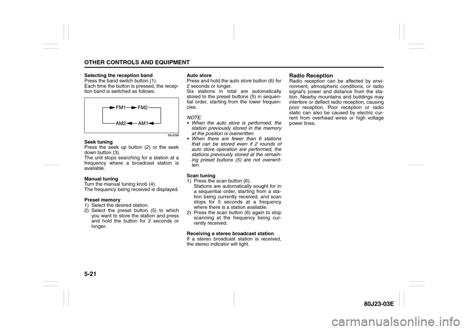
Selecting the reception band
Press the band switch button (1).
Each time the button is pressed, the recep-
tion band is switched as follows:
66J098
Seek tuning
Press the seek up button (2) or the seek
down button (3).
The unit stops searching for a station at a
frequency where a broadcast station is
available.
Manual tuning
Turn the manual tuning knob (4).
The frequency being received is displayed.
Preset memory
1) Select the desired station.
2) Select the preset button (5) to which
you want to store the station and press
and hold the button for 2 seconds or
longer.Auto store
Press and hold the auto store button (6) for
2 seconds or longer.
Six stations in total are automatically
stored to the preset buttons (5) in sequen-
tial order, starting from the lower frequen-
cies.
NOTE:
When the auto store is performed, the
station previously stored in the memory
at the position is overwritten.
When there are fewer than 6 stations
that can be stored even if 2 rounds of
auto store operation are performed, the
stations previously stored at the remain-
ing preset buttons (5) are not overwrit-
ten.
Scan tuning
1) Press the scan button (6).
Stations are automatically sought for in
a sequential order, starting from a sta-
tion being currently received, and scan
stops for 5 seconds at a frequency
where there is a station available.
2) Press the scan button (6) again to stop
scanning at the frequency being cur-
rently received.
Receiving a stereo broadcast station
If a stereo broadcast station is received,
the stereo indicator will light.
Radio ReceptionRadio reception can be affected by envi-
ronment, atmospheric conditions, or radio
signal’s power and distance from the sta-
tion. Nearby mountains and buildings may
interfere or deflect radio reception, causing
poor reception. Poor reception or radio
static can also be caused by electric cur-
rent from overhead wires or high voltage
power lines.