2010 SUBARU TRIBECA sensor
[x] Cancel search: sensorPage 169 of 422

3-40Instruments and controls
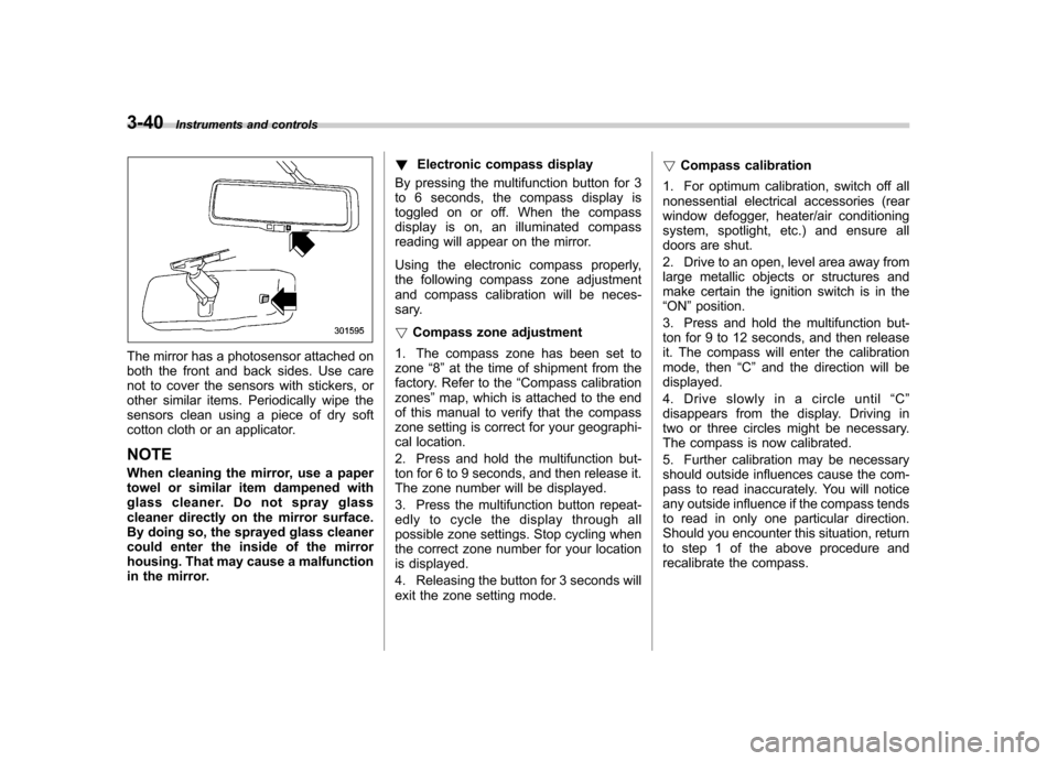
The mirror has a photosensor attached on
both the front and back sides. Use care
not to cover the sensors with stickers, or
other similar items. Periodically wipe the
sensors clean using a piece of dry soft
cotton cloth or an applicator. NOTE
When cleaning the mirror, use a paper
towel or similar item dampened with
glass cleaner. Do not spray glass
cleaner directly on the mirror surface.
By doing so, the sprayed glass cleaner
could enter the inside of the mirror
housing. That may cause a malfunction
in the mirror. !
Electronic compass display
By pressing the multifunction button for 3
to 6 seconds, the compass display is
toggled on or off. When the compass
display is on, an illuminated compass
reading will appear on the mirror.
Using the electronic compass properly,
the following compass zone adjustment
and compass calibration will be neces-
sary. ! Compass zone adjustment
1. The compass zone has been set to zone “8 ” at the time of shipment from the
factory. Refer to the “Compass calibration
zones ”map, which is attached to the end
of this manual to verify that the compass
zone setting is correct for your geographi-
cal location.
2. Press and hold the multifunction but-
ton for 6 to 9 seconds, and then release it.
The zone number will be displayed.
3. Press the multifunction button repeat-
edly to cycle the display through all
possible zone settings. Stop cycling when
the correct zone number for your location
is displayed.
4. Releasing the button for 3 seconds will
exit the zone setting mode. !
Compass calibration
1. For optimum calibration, switch off all
nonessential electrical accessories (rear
window defogger, heater/air conditioning
system, spotlight, etc.) and ensure all
doors are shut.
2. Drive to an open, level area away from
large metallic objects or structures and
make certain the ignition switch is in the“ ON ”position.
3. Press and hold the multifunction but-
ton for 9 to 12 seconds, and then release
it. The compass will enter the calibration
mode, then “C ” and the direction will be
displayed.
4. Drive slowly in a circle until “C ”
disappears from the display. Driving in
two or three circles might be necessary.
The compass is now calibrated.
5. Further calibration may be necessary
should outside influences cause the com-
pass to read inaccurately. You will notice
any outside influence if the compass tends
to read in only one particular direction.
Should you encounter this situation, return
to step 1 of the above procedure and
recalibrate the compass.
Page 170 of 422

&Type C inside mirror (if equipped)
1) Left button
2) Auto dimming indicator
3) Photosensor
4) Right button
This mirror has an anti-glare feature which
automatically reduces glare coming from
headlights of vehicles behind you. It also
contains a built-in compass. . By pressing and releasing the left
button, the automatic dimming function is
toggled on or off. When the automatic
dimming function is on, the auto dimming
indicator light (green) located to the right
of the button will illuminate. . By pressing and releasing the right
button, the compass display is toggled on or off. When the compass is on, an
illuminated compass reading will appear
in the lower part of the mirror.
Even with the mirror in anti-glare mode,
the mirror surface turns bright if the
transmission is shifted into reverse. This
is to ensure good rearward visibility duringreversing. !
Photosensors
The mirror has a photosensor attached on
both the front and back sides. If the glare
from the headlights of vehicles behind you
strikes the mirror, these sensors detect it
and make the reflection surface of the
mirror dimmer to help prevent you from
being blinded. For this reason, use care
not to cover the sensors with stickers, or
other similar items. Periodically wipe the sensors clean using a piece of dry soft
cotton cloth or an applicator. !
Compass calibration
1. For optimum calibration, switch off all
nonessential electrical accessories (rear
window defogger, heater/air conditioning
system, spotlight, etc.) and ensure all
doors are shut.
2. Drive to an open, level area away from
large metallic objects or structures and
make certain the ignition switch is in the“ ON ”position.
3. Press and hold the left button for 3
seconds then release, and the compass
will enter the calibration mode. “CAL ”and
direction will be displayed.
4. Drive slowly in a circle until “CAL ”
disappears from the display (approxi-
mately two or three circles). The compass
is now calibrated.
5. Further calibration may be necessary
should outside influences cause the mirror
to read inaccurately. You will know that
this has occurred if your compass begins
to read in only limited directions. Should
you encounter this situation, return to step
one of the above procedure and recali-
brate the mirror. Instruments and controls
3-41
– CONTINUED –
Page 174 of 422

Ventilator.............................................................. 4-2
Airflow ................................................................ 4-2
Ventilator ............................................................ 4-4
Automatic climate control system ..................... 4-5
Control panel ...................................................... 4-5
Rear air conditioner (if equipped) ......................... 4-8
Temperature sensors ........................................... 4-9
Operating tips for heater and air conditioner ....................................................... 4-10
Cleaning ventilator grille ..................................... 4-10
Efficient cooling after parking in direct sunlight ........................................................... 4-10 Lubrication oil circulation in the refrigerant
circuit .............................................................. 4-10
Checking air conditioning system before summer season ............................................................ 4-10
Cooling and dehumidifying in high humidity and low temperature weather conditions ................. 4-10
Air conditioner compressor shut-off when engine is heavily loaded .............................................. 4-10
Refrigerant for your climate control system ... ..... 4-10
Air filtration system ........................................... 4-11
Replacing the air filter ........................................ 4-11Climate control
4
Page 182 of 422

button on the control panel is in the“ON ”
position. The fan speed of the rear air
conditioner can be adjusted using the rear
air conditioner dial behind the center
console. The fan speed can be adjusted
in four steps by turning the dial. Turn the
dial to the “OFF ”position to stop the fan.
NOTE . When the “A/C ”button is in the
“ OFF ”position and when the “A/C ”
indicator is not illuminated during
AUTO mode operation, the air condi-
tioner compressor does not operate,
meaning that the system merely blows
uncooled air out of the ventilators.. The outlet air temperature of the rear
air conditioner cannot be adjusted.. The rear air conditioner cannot be
used as a heater. &
Temperature sensors
1) Interior air temperature sensor
2) Solar sensor
The automatic climate control system
employs several sensors. These sensors
are delicate. If they are treated incorrectly
and become damaged, the system may
not be able to control the interior tempera-
ture correctly. To avoid damaging the
sensors, observe the following precau-tions. – Do not subject the sensors to impact.
– Keep water away from the sensors.
– Do not cover the sensors.
The sensors are located as follows.– Solar sensor: beside windshield
defroster grille –
Interior air temperature sensor: on the
side of the driver-side part of the center panel – Outside temperature sensor: behind
front grille Climate control
4-9
Page 271 of 422

7-28Starting and operating
Tire pressure monitoring
system (TPMS)
The tire pressure monitoring system pro-
vides the driver with a warning message
by sending a signal from a sensor that is
installed in each wheel when tire pressure
is severely low.
The tire pressure monitoring system will
activate only when the vehicle is driven at
speeds above 20 mph (32 km/h). Also,
this system may not react immediately to a
sudden drop in tire pressure (for example,
a blow-out caused by running over a
sharp object).
WARNING
If the low tire pressure warning light
illuminates while driving, never
brake suddenly and keep driving
straight ahead while gradually redu-
cing speed. Then slowly pull off the
road to a safe place. Otherwise an
accident involving serious vehicle
damage and serious personal injury
could occur.
Check the pressure for all four tires
and adjust the pressure to the COLD
tire pressure shown on the tire
placard on the door pillar on thedriver ’s side.
Even when the vehicle is driven a
very short distance, the tires get
warm and their pressures increase
accordingly. Be sure to let the tires
cool thoroughly before adjusting
their pressures to the standard
values shown on the tire placard.
Refer to “Tires and wheels ”F 11-24.
The tire pressure monitoring system
does not function when the vehicle
is stationary. After adjusting the tire
pressures, increase the vehicle
speed to at least 20 mph (32 km/h)
to start the TPMS re-checking of the
tire inflation pressures. If the tire
pressures are now above the severe low pressure threshold, the low tire
pressure warning light should turn
off a few minutes later.
If this light still illuminates while
driving after adjusting the tire pres-
sure, a tire may have significant
damage and a fast leak that causes
the tire to lose air rapidly. If you have
a flat tire, replace it with a spare tire
as soon as possible.
When a spare tire is mounted or a
wheel rim is replaced without the
original pressure sensor/transmitter
being transferred, the low tire pres-
sure warning light will illuminate
steadily after blinking for approxi-
mately one minute. This indicates
the TPMS is unable to monitor all
four road wheels. Contact your
SUBARU dealer as soon as possible
for tire and sensor replacement and/
or system resetting.
Do not inject any tire liquid or
aerosol tire sealant into the tires,
as this may cause a malfunction of
the tire pressure sensors. If the light
illuminates steadily after blinking for
approximately one minute, promptly
contact a SUBARU dealer to have
the system inspected.
Page 310 of 422

of the tire facing up).
3. Turn the hoist shaft end clockwise with
the wheel nut wrench to wind the cable up
completely until you hear a few clicking
sounds. Confirm that the temporary spare
tire holding cable has been wound up
completely by shaking the temporary tire.
CAUTION
If the temporary spare tire is not
stored securely, it could damage
adjacent areas of the vehicle and
make an abnormal noise.
4. Place the wheel nut wrench and
extension back into the tool bag and store
the jack and tool bag in their storagelocations. 5. Fit the lid of the cargo area.
CAUTION
. When stowing a flat tire in the
spare tire holder, turn the hoist
shaft end only slowly. If it is
turned quickly, the wheel disc of
the flat tire could be damaged.
. A full-size flat tire should be
stowed in the spare tire holder
in an emergency only. After hav-
ing the flat tire repaired, immedi-
ately swap it with the temporary
spare tire.
. Remember that the tread width of
a flat tire is wider than that of the
temporary spare tire. When car-
rying a flat tire stowed in the
spare tire holder, make sure the
tire does not touch any obsta-cles. Temporary spare tire
WARNING
. Never tow a trailer when the
temporary spare tire is used.
The temporary spare tire is not
designed to sustain the towing
load. Use of the temporary spare
tire when towing can result in
failure of the spare tire and/or
less stability of the vehicle and
may lead to an accident.
. When a spare tire is mounted or a
wheel rim is replaced without the
original pressure sensor/trans-
mitter being transferred, the low
tire pressure warning light will
illuminate steadily after blinking
for approximately one minute.
This indicates the tire pressure
monitoring system (TPMS) is un-
able to monitor all four road
wheels. Contact your SUBARU
dealer as soon as possible for
tire and sensor replacement and/
or system resetting. In case of emergency
9-5
– CONTINUED –
Page 316 of 422

stop or collisions, loose equipment
could strike occupants and cause
injury. Store the tire and all tools in
the proper place.
& Tire pressure monitoring
system (TPMS)
The tire pressure monitoring system pro-
vides the driver with the warning message
indicated by sending a signal from a
sensor that is installed in each wheel
when tire pressure is severely low.
The tire pressure monitoring system will
activate only when the vehicle is driven.
Also, this system may not react immedi-
ately to a sudden drop in tire pressure (for
example, a blow-out caused running over
a sharp object).
WARNING
If the low tire pressure warning light
illuminates while driving, never
brake suddenly and keep driving
straight ahead while gradually redu-
cing speed. Then slowly pull off the
road to a safe place. Otherwise an
accident involving serious vehicle
damage and serious personal injury
could occur.
Check the pressure for all four tires
and adjust the pressure to the COLD
tire pressure shown on the vehicle
placard on the door pillar on thedriver ’s side. If this light still illumi-
nates while driving after adjusting
the tire pressure, a tire may have
significant damage and a fast leak
that causes the tire to lose air
rapidly. If you have a flat tire, replace
it with a spare tire as soon as possible.
When a spare tire is mounted or a
wheel rim is replaced without the
original pressure sensor/transmitter
being transferred, the low tire pres-
sure warning light will illuminate
steadily after blinking for approxi-
mately one minute. This indicates
the TPMS is unable to monitor all
four road wheels. Contact your SUBARU dealer as soon as possible
for tire and sensor replacement and/
or system resetting.
Do not inject any tire liquid or
aerosol tire sealant into the tires,
as this may cause a malfunction of
the tire pressure sensors.
If the light illuminates steadily after
blinking for approximately one min-
ute, promptly contact a SUBARU
dealer to have the system inspected.
In case of emergency
9-11
Page 328 of 422

NOTE
Be careful not to damage brake hoses,
sensor harnesses, and other parts
when washing suspension compo-nents. !Using a warm water washer
. Keep a good distance of 12 in (30 cm)
or more between the washer nozzle and
the vehicle. . Do not wash the same area continu-
ously.. If a stain will not come out easily, wash
by hand. Some warm water washers are
of the high temperature, high pressure
type, and they can damage or deform the
resin parts such as mouldings, or cause
water to leak into the vehicle. & Waxing and polishing
Always wash and dry the vehicle before
waxing and polishing.
Use a good quality polish and wax and
apply them according to the manufac-turer ’s instructions. Wax or polish when
the painted surface is cool.
Be sure to polish and wax the chrome trim,
as well as the painted surfaces. Loss of
wax on a painted surface leads to loss of
the original luster and also quickens the
deterioration of the surface. It is recom- mended that a coat of wax be applied at
least once a month, or whenever the
surface no longer repels water.
If the appearance of the paint has dimin-
ished to the point where the luster or tone
cannot be restored, lightly polish the
surface with a fine-grained compound.
Never polish just the affected area, but
include the surrounding area as well.
Always polish in only one direction. A
No. 2000 grain compound is recom-
mended. Never use a coarse-grained
compound. Coarser grained compounds
have a smaller grain-size number and
could damage the paint. After polishing
with a compound, coat with wax to restore
the original luster. Frequent polishing with
acompoundoranincorrectpolishing
technique will result in removing the paint
layer and exposing the undercoat. When
in doubt, it is always best to contact your
SUBARU dealer or an auto paint specia-list.
NOTE
Be careful not to block the windshield
washer nozzles with wax when waxing
the vehicle. &
Cleaning aluminum wheels
. Promptly wipe the aluminum wheels
clean of any kind of grime or agent. If dirt
is left on too long, it may be difficult to
clean off. . Do not use soap containing grit to
clean the wheels. Be sure to use a neutral
cleaning agent, and later rinse thoroughly
with water. Do not clean the wheels with a
stiff brush or expose them to a high-speed
washing device. . Clean the vehicle (including the alumi-
num wheels) with water as soon as
possible when it has been splashed with
sea water, exposed to sea breezes, or
driven on roads treated with salt or otheragents. Appearance care
10-3