2010 SUBARU OUTBACK tow
[x] Cancel search: towPage 325 of 448
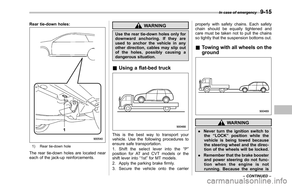
Rear tie-down holes:
1) Rear tie-down hole
The rear tie-down holes are located near
each of the jack-up reinforcements.
WARNING
Use the rear tie-down holes only for
downward anchoring. If they are
used to anchor the vehicle in any
other direction, cables may slip out
of the holes, possibly causing a
dangerous situation.
& Using a flat-bed truck
This is the best way to transport your
vehicle. Use the following procedures to
ensure safe transportation.
1. Shift the select lever into the “P ”
position for AT and CVT models or the
shift lever into “1st ”for MT models.
2. Apply the parking brake firmly.
3. Secure the vehicle onto the carrier properly with safety chains. Each safety
chain should be equally tightened and
care must be taken not to pull the chains
so tightly that the suspension bottoms out.
& Towing with all wheels on the ground
WARNING
. Never turn the ignition switch to
the “LOCK ”position while the
vehicle is being towed because
the steering wheel and the direc-
tion of the wheels will be locked.
. Remember that the brake booster
and power steering do not func-
tion when the engine is not
running. Because the engine is In case of emergency
9-15
– CONTINUED –
Page 326 of 448
9-16In case of emergency
turned off, it will take greater
effort to operate the brake pedal
and steering wheel.
CAUTION
. If transmission failure occurs,
transport your vehicle on a flat-
bed truck.
. Do not run the engine while being
towed using this method. Trans-
mission damage could result if
the vehicle is towed with the
engine running.
. For AT and CVT models, the
traveling speed must be limited
to less than 20 mph (30 km/h) and
the traveling distance to less
than 31 miles (50 km). For greater
speeds and distances, transport
your vehicle on a flat-bed truck.
1. Check the transmission and differen-
tial oil levels and add oil to bring it to the
upper level if necessary.
2. Release the parking brake and put the
transmission in neutral.
3. The ignition switch should be in the “ Acc ”position while the vehicle is being
towed.
4. Take up slack in the towline slowly to prevent damage to the vehicle.
Electronic parking brake–if
the electronic parking brake
cannot be releasedWARNING
. When the electronic parking
brake cannot be released, the
electronic parking brake system
may malfunction. Driving in such
conditions may cause an unex-
pected accident. Contact your
SUBARU dealer for inspection
as soon as possible.
. You can release the electronic
parking brake by using the elec-
tronic parking brake release tool
in case of an emergency. How-
ever, after releasing the electro-
nic parking brake by using the
electronic parking brake release
tool, contact your SUBARU deal-
er for inspection as soon aspossible.
. Release the electronic parking
brakebyusingtheelectronic
parking brake release tool on a
level road. Otherwise, the vehicle
may move, which could cause anaccident.
Page 344 of 448
11-8Maintenance and service
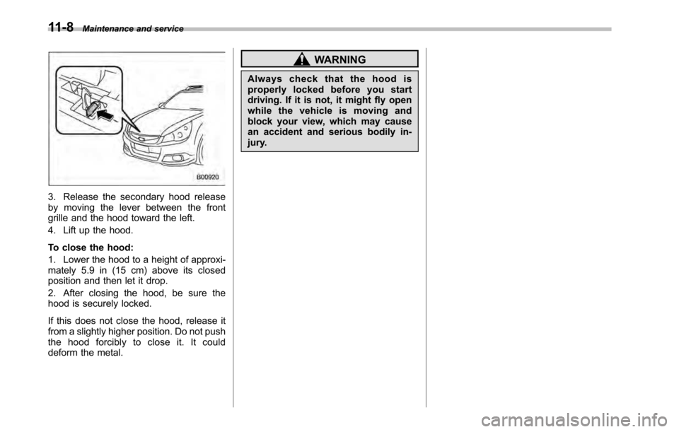
3. Release the secondary hood release
by moving the lever between the front
grille and the hood toward the left.
4. Lift up the hood.
To close the hood:
1. Lower the hood to a height of approxi-
mately 5.9 in (15 cm) above its closed
position and then let it drop.
2. After closing the hood, be sure the
hood is securely locked.
If this does not close the hood, release it
from a slightly higher position. Do not push
the hood forcibly to close it. It could
deform the metal.
WARNING
Always check that the hood is
properly locked before you start
driving. If it is not, it might fly open
while the vehicle is moving and
block your view, which may cause
an accident and serious bodily in-
jury.
Page 353 of 448
&Recommended grade and
viscosity under severe driv-
ing conditions
If the vehicle is used in desert areas, in
areas with very high temperatures, or
used for heavy-duty applications such as
towing a trailer, use of oil with the following
grade and viscosities is recommended.
API classification SM or SL: SAE viscosity No.:30, 40, 10W-50, 20W-40, 20W-50 Cooling system
WARNING
Never attempt to remove the radia-
tor cap until the engine has been
shut off and has cooled down
completely. Since the coolant is
under pressure, you may suffer
serious burns from a spray of boil-
ing hot coolant when the cap isremoved.
CAUTION
. Vehicles are filled at the factory
with SUBARU Super Coolant that
does not require the first change
for 11 years/137,500 miles (11
years/220,000 km). This coolant
should not be mixed with any
other brand or type of coolant
during this period. Mixing with a
different coolant will reduce the
life of the coolant. Should it be
necessary to top off the coolant
for any reason, use only
SUBARU Super Coolant.
If the SUBARU Super Coolant is
diluted with another brand or
type, the maintenance interval is shortened to that of the mixingcoolant.
. Do not splash the engine coolant
over painted parts. The alcohol
contained in the engine coolant
may damage the paint surface.
& Cooling fan, hose and con- nections
Your vehicle employs an electric cooling
fan which is thermostatically controlled to
operate when the engine coolant reaches
a specific temperature.
If the radiator cooling fan does not operate
even when the coolant temperature high
warning light illuminates, the cooling fan
circuit may be defective. Check the fuse
and replace it if necessary. Refer to“ Fuses ”F 11-48 and “Fuses and circuits ”
F 12-6. If the fuse is not blown, have the
cooling system checked by your SUBARU
dealer.
If frequent addition of coolant is neces-
sary, there may be a leak in the engine
cooling system. It is recommended that
the cooling system and connections be
checked for leaks, damage, or looseness. Maintenance and service
11-17
– CONTINUED –
Page 382 of 448
11-46Maintenance and service
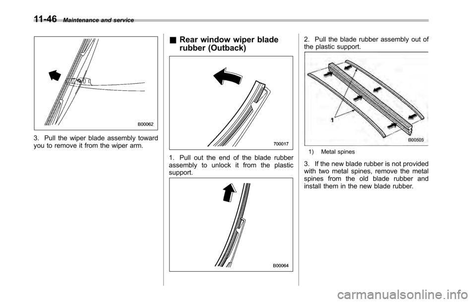
3. Pull the wiper blade assembly toward
you to remove it from the wiper arm. &
Rear window wiper blade
rubber (Outback)
1. Pull out the end of the blade rubber
assembly to unlock it from the plasticsupport.
2. Pull the blade rubber assembly out of
the plastic support.
1) Metal spines
3. If the new blade rubber is not provided
with two metal spines, remove the metal
spines from the old blade rubber and
install them in the new blade rubber.
Page 421 of 448
&Tire care –maintenance and
safety practices
. Check on a daily basis that the
tires are free from serious damage,
nails, and stones. At the same time,
check the tires for abnormal wear.
. Inspect the tire tread regularly
and replace the tires before their
tread wear indicators become visi-
ble. When a tire ’streadwear
indicator becomes visible, the tire
is worn beyond the acceptable limit
and must be replaced immediately.
With a tire in this condition, driving
at even low speeds in wet weather
can cause the vehicle to hydro-
plane. Possible resulting loss of
vehiclecontrolcanleadtoanaccident.
. To maximize the life of each tire
and ensure that the tires wear
uniformly, it is best to rotate the
tires every 7,500 miles (12,000 km).
Rotating the tires involves switch-
ing the front and rear tires on the
right-hand side of the vehicle and
similarly switching the front and rear tires on the left-hand side of
the vehicle. (Each tire must be kept
on its original side of the vehicle.)
Replace any damaged or unevenly
worn tire at the time of rotation.
After tire rotation, adjust the tire
pressures and make sure the wheel
nuts are correctly tightened. For
information about the tightening
torque and tightening sequence
for the wheel nuts, refer to
“Flat
tires ”F 9-6 .
& Vehicle load limit –how to
determine
The load capacity of your vehicle is
determined by weight, not by avail-
able cargo space. The load limit of
your vehicle is shown on the
vehicle placard attached to the
driver ’s side B-pillar. Locate the
statement “The combined weight
of occupants and cargo should
never exceed XXX kg or XXX lbs ”
on your vehicle ’s placard.
Thevehicleplacardalsoshows
seating capacity of your vehicle. The total load capacity includes the
total weight of driver and all pas-
sengers and their belongings, any
cargo, any optional equipment such
as a trailer hitch, roof rack or bike
carrier, etc., and the tongue load of
a trailer. Therefore cargo capacity
can be calculated by the following method.
Cargo capacity = Load limit
�(total
weight of occupants + total weight
of optional equipment + tongue
load of a trailer (if applicable))
For towing capacity information and
weight limits, refer to “Trailer tow-
ing ”F 8-19 .
Consumer information and Reporting safety defects
13-11
– CONTINUED –
Page 425 of 448
.Vehicle stability will deteriorate.
. Heavy and/or high-mounted
loads could increase the risk of
rollover.
. Stopping distance will increase.
. Brakes could overheat and fail.
. Suspension, bearings, axles and
other parts of the body could break
or experience accelerated wear
that will shorten vehicle life.
. Tires could fail.
. Tread separation could occur.
. Tire could separate from its rim.
& Steps for Determining Cor-
rect Load Limit
1. Locate the statement “The com-
bined weight of occupants and
cargo should never exceed XXXpounds ”on your vehicle ’s placard.
2. Determine the combined weight
of the driver and passengers that
will be riding in your vehicle.
3. Subtract the combined weight of
the driver and passengers from
XXX kilograms or XXX pounds.
4. The resulting figure equals the available amount of cargo and
luggage load capacity. For exam-
ple, if the
“XXX ”amount equals
1,400 lbs (635 kg) and there will be
five- 150 lbs (68 kg) passengers in
your vehicle, the amount of avail-
able cargo and luggage load capa-
city is 650 lbs (1,400 �750 (5 6
150) = 650 lbs).
5. Determine the combined weight
of luggage and cargo being loaded
on the vehicle. That weight may not
safely exceed the available cargo
and luggage load capacity calcu-
lated in Step 4.
6. If your vehicle will be towing a
trailer, load from your trailer will be
transferred to your vehicle. Consult
this manual to determine how this
reduces the available cargo and
luggage load capacity of your ve-hicle. Uniform tire quality grading
standards
This information indicates the rela-
tive performance of passenger car
tires in the area of treadwear,
traction, and temperature resis-
tance. This is to aid the consumer
in making an informed choice in the
purchase of tires.
Quality grades can be found where
applicable on the tire sidewall be-
tween tread shoulder and maxi-
mum section width. For example:
Treadwear 200 Traction AA Tem-
perature A
The quality grades apply to new
pneumatic tires for use on passen-
ger cars. However, they do not
apply to deep tread, winter type
snow tires, space-saver or tempor-
ary use spare tires, tires with
nominal rim diameters of 12 inches
or less, or to some limited produc-
tion tires.
All passenger car tires must con-
Consumer information and Reporting safety defects
13-15
– CONTINUED –
Page 434 of 448
14-6Index
Front seat ............................................................... 1-5
Rear seat .............................................................. 1-10
Headlight ......................................................... 3-27, 11-50
Flasher ................................................................. 3-28
Indicator light ......................................................... 3-23
Heater operation (manual climate control system) .. .......... 4-6
High beam indicator light ............................................ 3-23
High/low beam change (dimmer) .................................. 3-28
Hill Holder ................................................................. 7-35
Indicator light ................................................. 3-19, 7-36
Switch .................................................................. 7-35
Hook Coat ..................................................................... 6-13
Convenient tie-down ............................................... 6-17
Shopping bag ........................................................ 6-14
Towing and tie-down ............................................... 9-13
Horn ......................................................................... 3-39
Hose and connections ............................................... 11-17
I
Ignition switch .............................................................. 3-3
Light ....................................................................... 3-4
Illumination brightness control ...................................... 3-30
Immobilizer. ................................................................. 2-3
Indicator light (security indicator light) ................. 2-4, 3-22
Indicator light Coolant temperature low ......................................... 3-13
Cruise control ................................................ 3-23, 7-41
Cruise control set ........................................... 3-23, 7-41
Door open ............................................................. 3-20
Front fog light ........................................................ 3-23 Headlight
............................................................... 3-23
High beam ............................................................. 3-23
Security .......................................................... 2-4, 3-22
Select lever/Gear position ........................................ 3-22
Turn signal ............................................................ 3-23
Vehicle Dynamics Control OFF ......................... 3-21, 7-31
Vehicle Dynamics Control operation .. ................ 3-21, 7-30
Inside mirror .............................................................. 3-36
Interior lights ............................................................... 6-2
Internal trunk lid release handle .................................... 2-25
J
Jack-up point .............................................................. 9-6
Jump starting ............................................................. 9-10
K
Key............................................................................ 2-2 Number .................................................................. 2-2
Reminder chime ...................................................... 3-4
Replacement. .......................................................... 2-4
Keyless entry system ................................................... 2-8
L
Leather seat materials ................................................. 10-5
License plate light ..................................................... 11-57
Light Back-up (Legacy) ................................................. 11-54
Brake (Outback) ................................................... 11-55
Brake/Tail and rear side marker (Legacy). ................ 11-54
Cargo area .................................................... 6-3, 11-60
Control switch ........................................................ 3-27