2010 SUBARU OUTBACK ECU
[x] Cancel search: ECUPage 215 of 448

First menu Second menu Third menuDetails
Setup Security Set Pin Setting a PIN code
Phbk Lock Locking the phonebook*
Phbk Unlock Unlocking the phonebook*
Go Back
Phone setup Pair Phone Registering a new cell phone
Select Phone Selecting a cell phone to be used
Change Name Changing the registered name of the cell phone
List Phones Showing the list of the registered cell phones
Set Passkey Changing the pass key
Delete Deleting the registered cell phone
Go Back
System setup Guidance Vol Setting the volume of the voice guidance
Initialize Initialization
Go Back
Go Back —
*: If a PIN code is not registered, the menu described in the chart is not available. Audio
5-39
– CONTINUED –
Page 216 of 448
5-40Audio
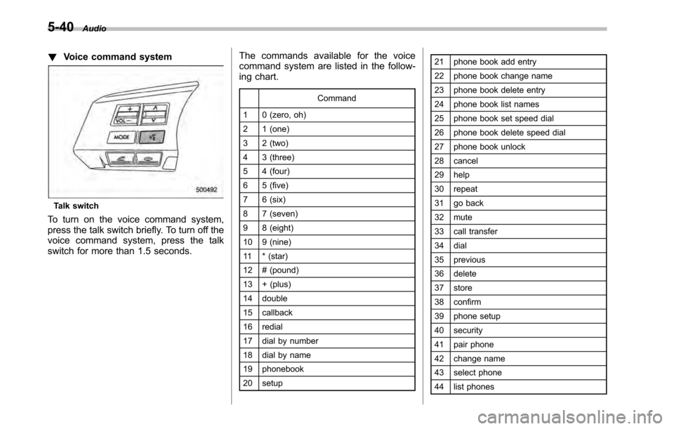
!Voice command system
Talk switch
To turn on the voice command system,
press the talk switch briefly. To turn off the
voice command system, press the talk
switch for more than 1.5 seconds. The commands available for the voice
command system are listed in the follow-
ing chart.
Command
1 0 (zero, oh)
2 1 (one)
3 2 (two)
4 3 (three)
5 4 (four)
6 5 (five)
7 6 (six)
8 7 (seven)
9 8 (eight)
10 9 (nine)
11 * (star)
12 # (pound)
13 + (plus)
14 double
15 callback
16 redial
17 dial by number
18 dial by name
19 phonebook
20 setup 21 phone book add entry
22 phone book change name
23 phone book delete entry
24 phone book list names
25 phone book set speed dial
26 phone book delete speed dial
27 phone book unlock
28 cancel
29 help
30 repeat
31 go back
32 mute
33 call transfer
34 dial
35 previous
36 delete
37 store
38 confirm
39 phone setup
40 security
41 pair phone
42 change name
43 select phone
44 list phones
Page 233 of 448
CAUTION
Make sure the driver ’s floor mat is
placed back in its proper location
and correctly secured on its retain-
ing pin. Also, do not use more than
one floor mat. If the floor mat slips
forward and interferes with the
movement of the pedals during
driving, it could cause an accident. Cargo area cover
(if equipped)
The cargo area cover is provided for
covering the cargo area and to protect its
contents from direct sunlight. This cover is
detachable to make room for additionalcargo. &
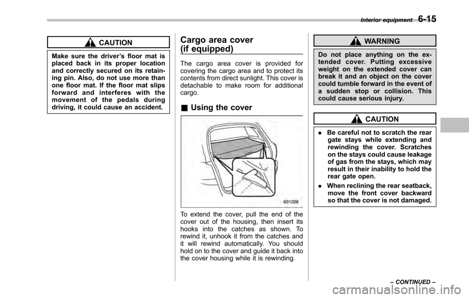
Using the cover
To extend the cover, pull the end of the
cover out of the housing, then insert its
hooks into the catches as shown. To
rewind it, unhook it from the catches and
it will rewind automatically. You should
hold on to the cover and guide it back into
the cover housing while it is rewinding.
WARNING
Do not place anything on the ex-
tended cover. Putting excessive
weight on the extended cover can
break it and an object on the cover
could tumble forward in the event of
a sudden stop or collision. This
could cause serious injury.
CAUTION
. Be careful not to scratch the rear
gate stays while extending and
rewinding the cover. Scratches
on the stays could cause leakage
of gas from the stays, which may
result in their inability to hold the
rear gate open.
. When reclining the rear seatback,
move the front cover backward
so that the cover is not damaged. Interior equipment
6-15
– CONTINUED –
Page 235 of 448

&To install the cover housing
1. To install the cover housing, insert
both ends of the cover housing into theretainers.
2. Make sure to fix the front part of the cargo area cover behind the rear seat.
Convenient tie-down hooks
(if equipped)
CAUTION
The convenient tie-down hooks are
designed only for securing light
cargo. Never try to secure cargo
that exceeds the capacity of the
hooks. The maximum load capacity
is 44 lbs (20 kg) per hook.
The cargo area is equipped with four tie-
down hooks so that cargo can be secured
with a luggage net or ropes.
When using the tie-down hooks, turn them
down out of the storing recesses. When
not in use, put the hooks up into the Interior equipment
6-17
– CONTINUED –
Page 247 of 448
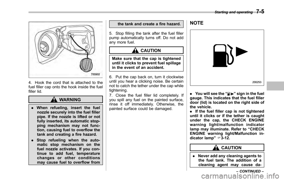
4. Hook the cord that is attached to the
fuel filler cap onto the hook inside the fuel
filler lid.
WARNING
. When refueling, insert the fuel
nozzle securely into the fuel filler
pipe. If the nozzle is lifted or not
fully inserted, its automatic stop-
ping mechanism may not func-
tion, causing fuel to overflow the
tank and creating a fire hazard.
. Stop refueling when the auto-
matic stop mechanism on the
fuel nozzle activates. If you con-
tinue to add fuel, temperature
changes or other conditions
may cause fuel to overflow from the tank and create a fire hazard.
5. Stop filling the tank after the fuel filler
pump automatically turns off. Do not add
any more fuel.
CAUTION
Make sure that the cap is tightened
until it clicks to prevent fuel spillage
in the event of an accident.
6. Put the cap back on, turn it clockwise
until you hear a clicking noise. Be certain
not to catch the tether under the cap whiletightening.
7. Close the fuel filler lid completely. If
you spill any fuel on the painted surface,
rinse it off immediately. Otherwise, the
painted surface could be damaged. NOTE
.
You will see the “”sign in the fuel
gauge. This indicates that the fuel filler
door (lid) is located on the right side of
the vehicle.. If the fuel filler cap is not tightened
until it clicks or if the tether is caught
under the cap, the CHECK ENGINE
warning light/malfunction indicator
lamp may illuminate. Refer to “CHECK
ENGINE warning light/Malfunction in-
dicator lamp ”F 3-12.
CAUTION
. Never add any cleaning agents to
the fuel tank. The addition of a
cleaning agent may cause da- Starting and operating
7-5
– CONTINUED –
Page 248 of 448
7-6Starting and operating
mage to the fuel system.
. After refueling, turn the cap to the
right until it clicks to ensure that
it is fully tightened. If the cap is
not securely tightened, fuel may
leak out while the vehicle is being
driven or fuel spillage could
occur in the event of an accident,
creating a fire hazard.
. Do not let fuel spill on the exterior
surfaces of the vehicle. Because
fuel may damage the paint, be
sure to wipe off any spilled fuel
quickly. Paint damage caused by
spilled fuel is not covered under
the SUBARU Limited Warranty.
. Always use a genuine SUBARU
fuel filler cap. If you use the
wrong cap, it may not fit, and
your fuel tank and emission con-
trol system may be damaged. It
could also lead to fuel spillage
and a fire.
. Immediately put fuel in the tank
whenever the low fuel warning
light illuminates. Engine misfires
as a result of an empty tank
could cause damage to the en-gine. State emission testing (U.S. only)
WARNING
Testing of an All-Wheel Drive vehicle
must NEVER be performed on a
single two-wheel dynamometer. At-
tempting to do so will result in
uncontrolled vehicle movement and
may cause an accident or injuries to
persons nearby.
CAUTION
Resultant vehicle damage due to
improper testing is not covered
under the SUBARU Limited War-
ranty and is the responsibility of
the state inspection program or its
contractors or licensees.
At state inspection time, remember to
tell your inspection or service station in
advance not to place your SUBARU
AWD vehicle on a two-wheel dynam-
ometer. Otherwise, serious transmis-
sion damage will result.
Some states have started using dynam-
ometers in their state inspection programs in order to meet their obligation under
federal law to implement stricter vehicle
emission standards to reduce air pollution
from vehicles. A dynamometer is a tread-
mill or roller-like testing device that allows
your vehicle
’s wheels to turn while the
vehicle remains in one place. Depending
on the severity of a state ’s air pollution
problems, the states must adopt either a“ basic ”or “enhanced ”vehicle emission
inspection test. Normally, a portion of the
basic emission test consists of an emis-
sion inspector inserting an analyzer probe
into the exhaust pipe of an idling vehicle
for a short period of time. States with more
severe air pollution problems are required
to adopt an enhanced vehicle emission
test. This test simulates actual driving
conditions on a dynamometer and permits
more accurate measurement of tailpipe
emitted pollution than the basic emissiontest.
The U.S. Environmental Protection
Agency (EPA) and states using two-wheel
dynamometers in their emission testing
programs have EXEMPTEDSUBARU
AWD vehicles from the portion of the
testing program that involves a two-wheel
dynamometer.
There are some states that use four-wheel
dynamometers in their testing programs.
When properly used, that equipment will
Page 253 of 448

&Starting your vehicle
NOTE
All vehicle doors, the engine hood and
trunk / rear gate must be closed prior to
activating the remote engine start sys-
tem. Any open entry point will prevent
starting or cause the system to shutdown.
The remote engine start function is acti-
vated by pressing the “
”button twice
within 3 seconds on your remote engine
start transmitter. Upon successful activa-
tion the remote start confirming transmitter
button will flash once* and the vehicle will
honk the horn and flash the side marker
lights, tail lights and front position lights
once. The system will check certain preconditions before starting, and if all
safety parameters are correct, the engine
will start within 5 seconds. Upon success-
ful engine start, the remote start confirma-
tion transmitter button will flash twice
every 5 seconds* and the vehicle will
honk the horn and flash the side marker
lights, tail lights and the front position
lights once, then the lights will illuminate
and remain illuminated, indicating that the
engine is running. While the vehicle is
operating via the remote engine start
function, the power window features will
be disabled. Also, the system has a timer
and will shut down after 15 minutes if you
do not operate the vehicle. Press and hold the
“
”button for 2 seconds to turn the
engine off. The remote start confirmation
transmitter button will flash three times*
indicating that the engine has shut down.
If the starter cranks but does not start or
starts and stalls, the remote engine start
system will power off and then attempt to
start the engine an additional three times
unless the remote engine start system
determines that a vehicle malfunction is
preventing the system from starting. If the
engine does not start after additional
attempts, the remote engine start system
will abort and return to a non-activatestate.
*: Provided that the remote engine start transmitter is within the operating range of
the system.
& Remote start safety features
For safety and security reasons, the
system will fail to start and honk the horn
twice or shut down the engine during
remote start operation if any of the
following occur: . Any of the doors or the trunk / rear gate
are open / opened (*the vehicle ’s horn will
honk six times and the side marker lights,
tail lights and the front position lights will
flash six times indicating that a vehicle
door or trunk / rear gate was open when
the remote engine start system wasactivated). . The brake pedal is depressed
. The key was already in the ignition
switch. The engine hood is opened
. The remote start system “Service
mode ”is engaged
. The vehicle ’s engine idle speed has
reached a level over 3,500 RPM. The alarm is triggered by opening a
door or the rear gate.. The select lever is not in the “P ”
position (AT and CVT models)
In addition to the items above, if the Starting and operating
7-11
– CONTINUED –
Page 254 of 448
7-12Starting and operating
vehicle ’s engine management system
determines there is a safety risk due to a
vehicle related problem, the vehicle will
shut down and the vehicle ’s horn will honk
three times. NOTE . If the alarm system is armed at the
time of remote engine start activation
(the security indicator light on the
combination meter is flashing), the
alarm system will remain armed
throughout the remote start run cycle.. If the alarm system is disarmed at
the time of remote engine start activa-
tion (the security indicator light on the
combination meter is not flashing), the
alarm system will remain disarmed
throughout the remote start run cycle. & Entering the vehicle while it
is running via remote start
1. Unlock the vehicle doors using the
remote keyless entry system. If the vehi-cle ’s doors are unlocked manually using
the key, the vehicle ’s alarm system will
trigger (if the alarm system is armed prior
to activating the remote engine start
system) and the engine will turn off.
Inserting the key into the ignition switch
and turning it to the “ON ”position or
pressing the unlock button “
”on the remote keyless entry transmitter will dis-
arm the alarm system. Refer to
“Alarm
system ”F 2-16.
2. Enter the vehicle.
3. The engine will shut down when any
door or trunk/rear gate is opened.
4. Insert the key into the ignition switch
and turn to the “START ”position to restart
the engine.
& Remote start confirmation
transmitter feature
Your remote engine start transmitter is
equipped with a unique bidirectional con-
firmation feature. This feature will allow
the transmitter ’s backlit button to display
the status of the system under the condi-
tion that the vehicle and transmitter are
within the operational range of the system.
Typical transmitter button flash sequences
are outlined in the following chart.