2010 SUBARU OUTBACK warning
[x] Cancel search: warningPage 149 of 448

The indicator light located on the combi-
nation meter will illuminate when the front
fog lights are on.Wiper and washer
WARNING
In freezing weather, do not use the
windshield washer until the wind-
shield is sufficiently warmed by the
defroster.
Otherwise the washer fluid can
freeze on the windshield, blocking
your view.
CAUTION
. Do not operate the washer con-
tinuously for more than 10 sec-
onds, or when the washer fluid
tank is empty. This may cause
overheating of the washer motor.
Check the washer fluid level
frequently, such as at fuel stops.
. Do not operate the wipers when
the windshield or rear window is
dry. This may scratch the glass,
damage the wiper blades and
cause the wiper motor to burn
out. Before operating the wiper
on a dry windshield or rear
window, always use the wind-
shield washer. .
In freezing weather, be sure that
the wiper blades are not frozen to
the windshield or rear window
before switching on the wipers.
Attempting to operate the wiper
with the blades frozen to the
window glass could cause not
only the wiper blades to be
damaged but also the wiper mo-
tor to burn out. If the wiper
blades are frozen to the window
glass, be sure to operate the
defroster, wiper deicer (if
equipped) or rear window defog-
ger before turning on the wiper.
. If the wipers stop during opera-
tion because of ice or some other
obstruction on the window, the
wiper motor could burn out even
if the wiper switch is turned off. If
this occurs, promptly stop the
vehicle in a safe place, turn the
ignition switch to the “LOCK ”
position and clean the window
glass to allow proper wiper op-eration.
. Use clean water if windshield
washer fluid is unavailable. In
areas where water freezes in
winter, use SUBARU Windshield
Washer Fluid or the equivalent.
Refer to “Windshield washer
Instruments and controls
3-31
– CONTINUED –
Page 151 of 448

!Wiper intermittent time control
When the wiper switch is in the “INT ”
position, turn the dial to adjust the operat-
ing interval of the wiper. The operating
interval can be adjusted in five steps from
the shortest interval to the longest. !
Windshield washerTo wash the windshield, pull the wiper
control lever toward you. The washer fluid
sprays until you release the lever. The
wipers operate while you pull the lever. NOTE
The windshield washer fluid warning
light illuminates when the washer fluid
level in the tank has dropped to the
lower limit. If the warning light illumi-
nates, refill the tank with fluid. For the
tank refilling method, refer to
“Wind-
shield washer fluid ”F 11-42.
Instruments and controls
3-33
– CONTINUED –
Page 156 of 448
3-38Instruments and controls
&Outside mirrors
! Convex mirror (passenger side)
WARNING
Objects look smaller in a convex
mirror and farther away than when
viewed in a flat mirror. Do not use
the convex mirror to judge the
distance of vehicles behind you
when changing lanes. Use the inside
mirror (or glance backwards) to
determine the actual size and dis-
tance of objects that you view in
convex mirror. !
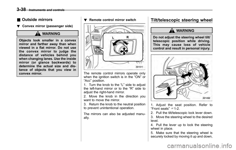
Remote control mirror switch
The remote control mirrors operate only
when the ignition switch is in the “ON ”or
“ Acc ”position.
1. Turn the knob to the “L ” side to adjust
the left-hand mirror or to the “R ” side to
adjust the right-hand mirror.
2. Move the knob in the direction you
want to move the mirror.
3. Return the knob to the neutral position
to prevent unintentional operation.
The mirrors can also be adjusted manu-
ally. Tilt/telescopic steering wheel
WARNING
Do not adjust the steering wheel tilt/
telescopic position while driving.
This may cause loss of vehicle
control and result in personal injury.
1. Adjust the seat position. Refer to “ Front seats ”F 1-2.
2. Pull the tilt/telescopic lock lever down.
3. Move the steering wheel to the desired level.
4. Pull the lever up to lock the steering
wheel in place.
5. Make sure that the steering wheel is
securely locked by moving it up and down,
Page 164 of 448
4-6Climate control
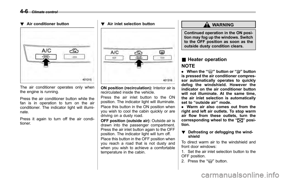
!Air conditioner button
The air conditioner operates only when
the engine is running.
Press the air conditioner button while the
fan is in operation to turn on the air
conditioner. The indicator light will illumi-nate.
Press it again to turn off the air condi-
tioner. !
Air inlet selection buttonON position (recirculation): Interior air is
recirculated inside the vehicle.
Press the air inlet button to the ON
position. The indicator light will illuminate.
Place this button in the ON position when
you wish to cool the cabin quickly or are
driving on a dusty road.
OFF position (outside air): Outside air is
drawn into the passenger compartment.
Press the air inlet button again to the OFF
position. The indicator light will turn off.
Place this button in the OFF position when
you reach a road that is not dusty and
when you wish to achieve a comfortable
temperature in the cabin.
WARNING
Continued operation in the ON posi-
tion may fog up the windows. Switch
to the OFF position as soon as the
outside dusty condition clears.
& Heater operation
NOTE . When the “
”button or “”button
is pressed the air conditioner compres-
sor automatically operates to quickly
defog the windshield. However the
indicator on the air conditioner button
will not illuminate. At the same time,
the air inlet selection is automatically
set to “outside air ”mode.
. Warm air also comes out from the
right and left air outlets. To stop warm
air flow from these outlets, turn the
corresponding wheel to the “
”posi-
tion. ! Defrosting or defogging the wind- shield
To direct warm air to the windshield and
front door windows:
1. Set the air inlet selection button to the
OFF position.
2. Press the “
”button.
Page 165 of 448
3. Turn the temperature control dial all
the way to the right.
4. Set the fan speed control dial to the
highest speed. !Heating and defrosting
To direct warm air toward the floor and the windshield:
1. Set the air inlet selection button to the
OFF position.
2. Press the “
”button.
3. Set the temperature control dial to the
most comfortable level.
4. Set the fan speed control dial to the
desired speed. ! Heating
To direct warm air toward the floor:
1. Set the air inlet selection button to the
OFF position.
2. Press the “
”button.
3. Set the temperature control dial to the
most comfortable level.
4. Set the fan speed control dial to the
desired speed. ! Bi-level heating
This setting allows you to direct air of
different temperatures from the instrument
panel and foot outlets. The air from the foot outlets is slightly warmer than from
the instrument panel outlets.
1. Set the air inlet selection button to the
OFF position.
2. Press the
“
”button.
3. Set the temperature control dial to the
desired temperature level.
4. Set the fan speed control dial to the
desired speed.
Setting the temperature control dial fully
turned to the red area or blue area
decreases the temperature difference
between the air from the instrument panel
outlets and the air from the foot outlets. ! Ventilation
To force outside air through the instrument
panel outlets:
1. Set the air inlet selection button to the
OFF position.
2. Press the “
”button.
3. Set the temperature control dial all the
way left.
4. Set the fan speed control dial to the
desired speed.
When driving on a dusty road, set the air
inlet control button to the ON position.
WARNING
Continued operation in the ON posi-
tion may fog up the windows. Switch
to the OFF position as soon as the
outside dusty condition clears.
& Air conditioner operation
! Cooling or dehumidifying
For cooling and dehumidification of the
passenger compartment, air flows through
the instrument panel outlets:
1. Set the air inlet selection button to the
OFF position.
2. Press the “
”button.
3. Set the air conditioner button to the “ ON ”position.
4. Set the temperature control dial to the
blue side.
5. Set the fan speed control dial at the
desired speed. ! Defrosting or defogging
To direct warm air to the windshield and
front door windows:
1. Press the “
”button.
2. Set the temperature control dial to the
red side.
3. Set the fan speed control dial at the
highest speed. Climate control
4-7
– CONTINUED –
Page 171 of 448

Press the air inlet selection button to the
OFF position when the interior has cooled
to a comfortable temperature and the road
is no longer dusty. The indicator light will
turn off.
WARNING
Continued operation in the ON posi-
tion (recirculation) may fog up the
windows. Switch to the OFF position
(outside air) as soon as the outside
dusty condition clears.
NOTE
When driving on a dusty road or behind
a vehicle that emits unpleasant exhaust
gases, set the air inlet selection button
to the ON position (recirculation).
From time to time, return the air inlet
selection button to the OFF position
(outside air) to draw outside air into the
passenger compartment. &
Temperature sensors
1) Solar sensor
2) Interior air temperature sensor
The automatic climate control system
employs several sensors. These sensors
are delicate. If they are treated incorrectly and become damaged, the system may
not be able to control the interior tempera-
ture correctly. To avoid damaging the
sensors, observe the following precau-tions: –
Do not subject the sensors to impact.
– Keep water away from the sensors.
– Do not cover the sensors.
The sensors are located as follows:– Solar sensor: beside windshield
defroster grille– Interior air temperature sensor: on the
side of the driver-side part of the center panel – Outside temperature sensor: behind
front grille. Climate control
4-13
Page 209 of 448
with it left in the breast pocket or bag. NOTE
The Hands-free system may not oper-
ate properly under the following condi-tions. .The cell phone is turned off.
. The cell phone is not in the phone
call area. . The battery of the call phone has run
down.. The cell phone is not connected to
the Hands-free system.. The cell phone is behind the seat or
in the glove box.. A metal material covers or touches
the cell phone. ! Corresponding profiles for the cell phone
. HFP (Hands Free Profile): Ver. 1.0
. OPP (Object Push Profile): Ver. 1.1
& Certification for the Hands-
free system
NOTE
This device complies with Part 15 of
the FCC Rules and with RSS-Gen of IC
Rules. Operation is subject to the
following two conditions: (1) This de-
vice may not cause harmful interfer- ence, and (2) this device must accept
any interference received, including
interference that may cause undesiredoperation.
Changes or modifications not ex-
pressly approved by the party respon-
sible for compliance could void theuser
’s authority to operate the equip-
ment.
NOTE
This equipment has been tested and
found to comply with the limits for a
Class B digital device, pursuant to Part
15 of the FCC Rules. These limits are
designed to provide reasonable protec-
tion against harmful interference in a
residential installation. This equipment
may cause harmful interference to
radio communications, if it is not
installed and used in accordance with
the instructions. However, there is no
guarantee that interference will not
occur in a particular installation. If this
equipment does cause harmful inter-
ference to radio or television reception,
which can be determined by turning the
equipment off and on, the user is
encouraged to try to correct the inter-
ference by one or more of the followingmeasures. .
Reorient or relocate the receiving
antenna.. Increase the separation between the
equipment and receiver.. Connect the equipment into an out-
let on a circuit different from that to
which the receiver is connected.. Consult the dealer or an experi-
enced radio/TV technician for help.
& Safety precautions
WARNING
. For safety reasons, avoid operat-
ing of the cell phone while driv- ing.
. Do not make a phone call while
driving. When you have an in-
coming call, stop the vehicle in a
safe location before taking the
incoming phone call. When you
have to absolutely take a phone
call, tell the caller “I’ll call you
back ”. And then call the caller
back after stopping the vehicle in
a safe location.
. Part 15 FCC Rules
FCC Warning:
Any unauthorized changes of
modifications to this equipment Audio
5-33
– CONTINUED –
Page 231 of 448
NOTE
Particles of ash and tobacco will accu-
mulate around the hinges of the ash-tray’s inner lid. Clean them off using a
toothbrush or another narrow-endedimplement. Coat hook
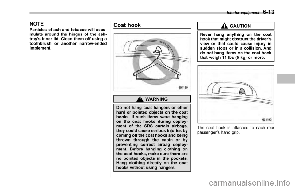
WARNING
Do not hang coat hangers or other
hard or pointed objects on the coat
hooks. If such items were hanging
on the coat hooks during deploy-
ment of the SRS curtain airbags,
they could cause serious injuries by
coming off the coat hooks and being
thrown through the cabin or by
preventing correct airbag deploy-
ment. Before hanging clothing on
the coat hooks, make sure there are
no pointed objects in the pockets.
Hang clothing directly on the coat
hooks without using hangers.
CAUTION
Never hang anything on the coat
hook that might obstruct the driver ’s
view or that could cause injury in
sudden stops or in a collision. And
do not hang items on the coat hook
that weigh 11 lbs (5 kg) or more.
The coat hook is attached to each rear passenger ’s hand grip. Interior equipment
6-13