2010 SUBARU LEGACY lock
[x] Cancel search: lockPage 220 of 448

6-2Interior equipment
Interior light
When leaving your vehicle, make sure the
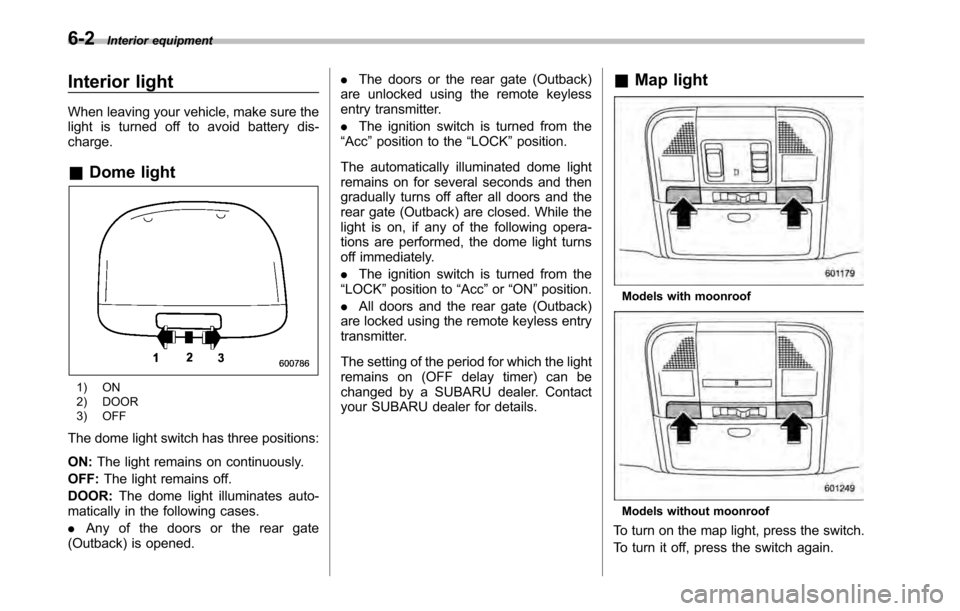
light is turned off to avoid battery dis-charge. &Dome light
1) ON
2) DOOR
3) OFF
The dome light switch has three positions: ON: The light remains on continuously.
OFF: The light remains off.
DOOR: The dome light illuminates auto-
matically in the following cases. . Any of the doors or the rear gate
(Outback) is opened. .
The doors or the rear gate (Outback)
are unlocked using the remote keyless
entry transmitter. . The ignition switch is turned from the
“ Acc ”position to the “LOCK ”position.
The automatically illuminated dome light
remains on for several seconds and then
gradually turns off after all doors and the
rear gate (Outback) are closed. While the
light is on, if any of the following opera-
tions are performed, the dome light turns
off immediately. . The ignition switch is turned from the
“ LOCK ”position to “Acc ”or “ON ”position.
. All doors and the rear gate (Outback)
are locked using the remote keyless entry
transmitter.
The setting of the period for which the light
remains on (OFF delay timer) can be
changed by a SUBARU dealer. Contact
your SUBARU dealer for details. &
Map light
Models with moonroof
Models without moonroof
To turn on the map light, press the switch.
To turn it off, press the switch again.
Page 221 of 448

When leaving the vehicle, make sure the
light is turned off to avoid battery dis-charge. !Door interlock switch
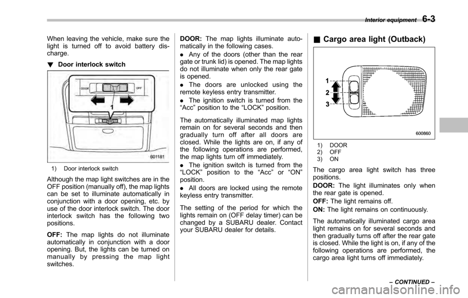
1) Door interlock switch
Although the map light switches are in the
OFF position (manually off), the map lights
can be set to illuminate automatically in
conjunction with a door opening, etc. by
use of the door interlock switch. The door
interlock switch has the following twopositions. OFF: The map lights do not illuminate
automatically in conjunction with a door
opening. But, the lights can be turned on
manually by pressing the map lightswitches. DOOR:
The map lights illuminate auto-
matically in the following cases. . Any of the doors (other than the rear
gate or trunk lid) is opened. The map lights
do not illuminate when only the rear gate
is opened. . The doors are unlocked using the
remote keyless entry transmitter.. The ignition switch is turned from the
“ Acc ”position to the “LOCK ”position.
The automatically illuminated map lights
remain on for several seconds and then
gradually turn off after all doors are
closed. While the lights are on, if any of
the following operations are performed,
the map lights turn off immediately. . The ignition switch is turned from the
“ LOCK ”position to the “Acc ”or “ON ”
position. . All doors are locked using the remote
keyless entry transmitter.
The setting of the period for which the
lights remain on (OFF delay timer) can be
changed by a SUBARU dealer. Contact
your SUBARU dealer for details. &
Cargo area light (Outback)
1) DOOR
2) OFF
3) ON
The cargo area light switch has three positions. DOOR: The light illuminates only when
the rear gate is opened.OFF: The light remains off.
ON: The light remains on continuously.
The automatically illuminated cargo area
light remains on for several seconds and
then gradually turns off after the rear gate
is closed. While the light is on, if any of the
following operations are performed, the
cargo area light turns off immediately. Interior equipment
6-3
– CONTINUED –
Page 222 of 448

6-4Interior equipment
.The ignition switch is turned from the
“ LOCK ”position to the “Acc ”or “ON ”
position. . The rear gate is locked using the
remote keyless entry transmitter.
The setting of the period for which the
lights remain on (OFF delay timer) can be
changed by a SUBARU dealer. Contact
your SUBARU dealer for details. Sun visors
To block out glare, swing down the visors.
To use the sun visor at a side window,
swing it down and move it sideways.&
Sun visor extension plateWith the sun visor positioned over the side
window, you can use the sun visor
extension plate to prevent glare through
the gap between the sun visor and center
pillar. To use the extension plate, pull it
toward the rear of the vehicle. When you
have finished using it, stow it by pushing it
toward the front of the vehicle.
Page 224 of 448

6-6Interior equipment
& Glove box
1) Lock
2) Unlock
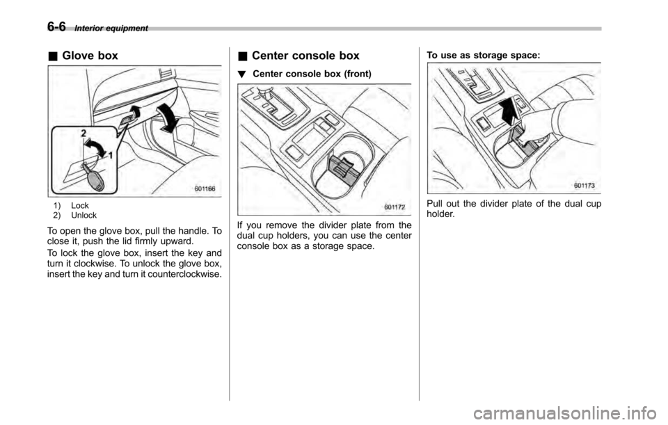
To open the glove box, pull the handle. To
close it, push the lid firmly upward.
To lock the glove box, insert the key and
turn it clockwise. To unlock the glove box,
insert the key and turn it counterclockwise. &
Center console box
! Center console box (front)
If you remove the divider plate from the
dual cup holders, you can use the center
console box as a storage space. To use as storage space:
Pull out the divider plate of the dual cup
holder.
Page 225 of 448

To use again as cup holders:
Insert the divider plate into the console box. !Center console box (rear)
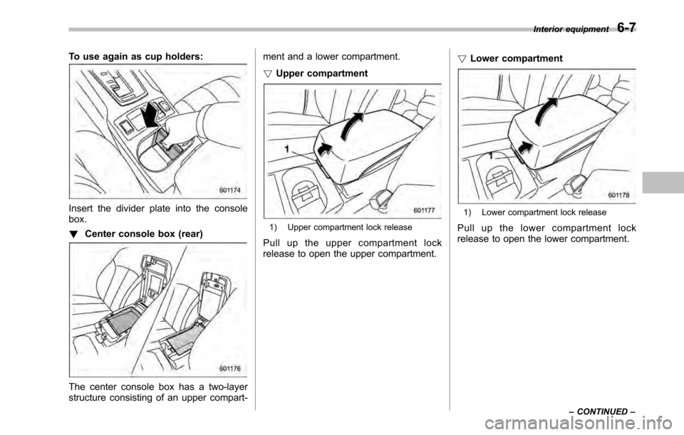
The center console box has a two-layer
structure consisting of an upper compart- ment and a lower compartment. !
Upper compartment
1) Upper compartment lock release
Pull up the upper compartment lock
release to open the upper compartment. !
Lower compartment
1) Lower compartment lock release
Pull up the lower compartment lock
release to open the lower compartment. Interior equipment
6-7
– CONTINUED –
Page 243 of 448

Fuel...................................................................... 7-2
Fuel requirements ............................................... 7-2
Fuel filler lid and cap ........................................... 7-3
State emission testing (U.S. only) ...................... 7-6
Preparing to drive ............................................... 7-7
Starting the engine .............................................. 7-8
MT models .......................................................... 7-8
AT and CVT models ............................................. 7-9
Stopping the engine ........................................... 7-10
Remote engine start system (dealer option) ................................................. 7-10
Starting your vehicle .......................................... 7-11
Remote start safety features ............................... 7-11
Entering the vehicle while it is running via remote start ................................................................. 7-12
Remote start confirmation transmitter feature ............................................................. 7-12
Entering the vehicle following remote engine start shutdown ......................................................... 7-13
Pre-heating or pre-cooling the interior of the vehicle ............................................................. 7-13
Service mode ..................................................... 7-14
Remote transmitter program ............................... 7-14
System maintenance .......................................... 7-14
Manual transmission .......................................... 7-16
Selecting reverse gear ........................................ 7-16
Shifting speeds .................................................. 7-17
Driving tips ........................................................ 7-17
Automatic transmission/Continuously variable transmission ..................................... 7-18
Select lever ........................................................ 7-19 Shift lock function
............................................. 7-20
Selection of manual mode .................................. 7-21
Driving tips ........................................................ 7-23
Power steering ................................................... 7-23
Braking ............................................................... 7-23
Braking tips ....................................................... 7-23
Brake system .................................................... 7-24
Disc brake pad wear warning indicators ............. 7-24
ABS (Anti-lock Brake System) .......................... 7-25
ABS system self-check ...................................... 7-25
ABS warning light .............................................. 7-25
Electronic Brake Force Distribution (EBD) system ............................................................. 7-26
Steps to take if EBD system malfunctions ..... ..... 7-27
Vehicle Dynamics Control system .................... 7-28
Vehicle Dynamics Control system monitor..... ..... 7-29
Vehicle Dynamics Control OFF switch ................ 7-31
Tire pressure monitoring system (TPMS) (if equipped) .................................................... 7-32
Parking your vehicle ......................................... 7-33
Electronic parking brake .................................... 7-34
Parking tips ....................................................... 7-37
Cruise control .................................................... 7-38
To set cruise control .......................................... 7-38
To temporarily cancel the cruise control ............. 7-39
To turn off the cruise control .............................. 7-39
To change the cruising speed .. .......................... 7-40
Cruise control indicator light .............................. 7-41
Cruise control set indicator light ........................ 7-41
Starting and operating
7
Page 246 of 448

7-4Starting and operating
1. To open the fuel filler lid, pull the lid
release lever up. The lever is on the floor
at the left of the driver ’s seat.
2. Open the fuel filler lid.
WARNING
Before opening the fuel filler cap,
first touch the vehicle body or a
metal portion of the fuel pump or
similar object to discharge any
static electricity that may be present
on your body. If your body is carry-
ing an electrostatic charge, there is
a possibility that an electric spark
could ignite the fuel, which could
burn you. To avoid acquiring a new
static electric charge, do not get
back into the vehicle while refueling
is in progress.
1) Open
2) Close
3. Remove the fuel filler cap by turning it slowly counterclockwise.
WARNING
. Gasoline vapor is highly flam-
mable. Before refueling, always
first stop the engine and close all
vehicle doors and windows.
Make sure that there are no
lighted cigarettes, open flames
or electrical sparks in the adja-
cent area. Refueling must be
performed outside. Quickly wipe
up any spilled fuel.
. When opening the cap, grasp it
firmly and turn it slowly to the
left. Do not remove the cap
quickly. Fuel may be under pres-
sure and spray out of the fuel
filler neck, especially in hot
weather. If you hear a hissing
sound while you are removing
the cap, wait for the sound to
stop and then slowly open the
cap to prevent fuel from spraying
out and creating a fire hazard.
Page 247 of 448

4. Hook the cord that is attached to the
fuel filler cap onto the hook inside the fuel
filler lid.
WARNING
. When refueling, insert the fuel
nozzle securely into the fuel filler
pipe. If the nozzle is lifted or not
fully inserted, its automatic stop-
ping mechanism may not func-
tion, causing fuel to overflow the
tank and creating a fire hazard.
. Stop refueling when the auto-
matic stop mechanism on the
fuel nozzle activates. If you con-
tinue to add fuel, temperature
changes or other conditions
may cause fuel to overflow from the tank and create a fire hazard.
5. Stop filling the tank after the fuel filler
pump automatically turns off. Do not add
any more fuel.
CAUTION
Make sure that the cap is tightened
until it clicks to prevent fuel spillage
in the event of an accident.
6. Put the cap back on, turn it clockwise
until you hear a clicking noise. Be certain
not to catch the tether under the cap whiletightening.
7. Close the fuel filler lid completely. If
you spill any fuel on the painted surface,
rinse it off immediately. Otherwise, the
painted surface could be damaged. NOTE
.
You will see the “”sign in the fuel
gauge. This indicates that the fuel filler
door (lid) is located on the right side of
the vehicle.. If the fuel filler cap is not tightened
until it clicks or if the tether is caught
under the cap, the CHECK ENGINE
warning light/malfunction indicator
lamp may illuminate. Refer to “CHECK
ENGINE warning light/Malfunction in-
dicator lamp ”F 3-12.
CAUTION
. Never add any cleaning agents to
the fuel tank. The addition of a
cleaning agent may cause da- Starting and operating
7-5
– CONTINUED –