2010 SUBARU FORESTER ad blue
[x] Cancel search: ad bluePage 124 of 402

take several driving trips. If the light does
not turn off, take your vehicle to your
authorized SUBARU dealer immediately. !If the light is blinking
If the light is blinking while driving, an
engine misfire condition has been de-
tected which may damage the emission
control system.
To prevent serious damage to the emis-
sion control system, you should do thefollowing. . Reduce vehicle speed.
. Avoid hard acceleration.
. Avoid steep uphill grades.
. Reduce the amount of cargo, if possi-
ble.
The CHECK ENGINE warning light may
stop blinking and illuminate steadily after
several driving trips. You should have your
vehicle checked by an authorized
SUBARU dealer immediately. &
Coolant temperature
low indicator light/Cool-
ant temperature high
warning light
CAUTION
. After turning the ignition switch
to the “ON ”position, if this
indicator light/warning light be-
haves under any of the following
conditions, the electrical system
may be malfunctioning. Contact
your SUBARU dealer immedi-
ately for an inspection. – It remains blinking in RED.
– It remains illuminated in RED
for more than 2 seconds.
– It remains blinking in RED and
BLUE alternately.
. While driving, if this indicator
light/warning light behaves under
any of the following conditions,
take the specified appropriate
measure listed below. – Blinking or illuminated in
RED:
Safely stop the vehicle as
soon as possible, and refer
to the emergency steps for the
engine overheating. After- ward, have the system
checked by your nearest
SUBARU dealer. Refer to
“En-
gine overheating ”F 9-12.
– Blinking in RED and BLUE
alternately:
The electrical system may be
malfunctioning. Contact your
SUBARU dealer for an inspec-tion.
This coolant temperature low indicator
light/coolant temperature high warning
light has the following three functions. . Illumination in BLUEindicates insuffi-
cient warming up of the engine. Blinking in REDindicates that the
engine is close to overheating. Illumination in REDindicates overheat-
ing condition of the engine
For the system check, this indicator light/
warning light illuminates in REDfor
approximately 2 seconds when the igni-
tion switch is turned to the “ON ”position.
After that, this indicator light/warning light
changes to BLUEand maintains illumina-
tion in BLUE. This BLUE illuminated light
turns off when the engine is warmed up
sufficiently.
If the engine coolant temperature in- Instruments and controls
3-13
– CONTINUED –
Page 158 of 402

&Center and side ventilators
! Center ventilators
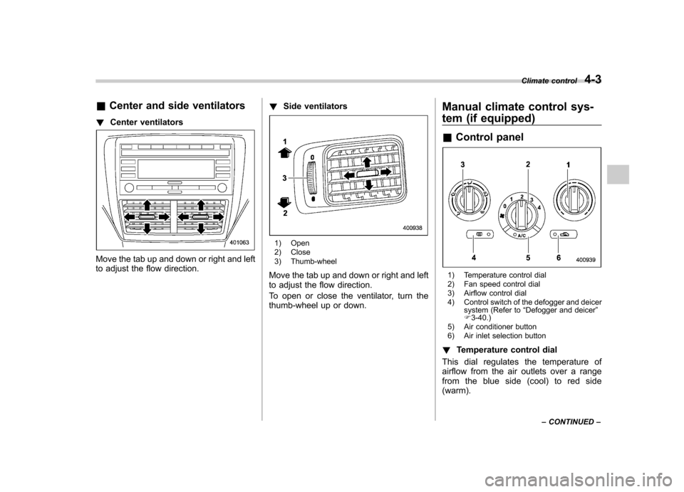
Move the tab up and down or right and left
to adjust the flow direction. !
Side ventilators
1) Open
2) Close
3) Thumb-wheel
Move the tab up and down or right and left
to adjust the flow direction.
To open or close the ventilator, turn the
thumb-wheel up or down. Manual climate control sys-
tem (if equipped) &
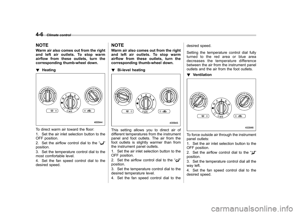
Control panel
1) Temperature control dial
2) Fan speed control dial
3) Airflow control dial
4) Control switch of the defogger and deicer
system (Refer to “Defogger and deicer ”
F 3-40.)
5) Air conditioner button
6) Air inlet selection button
! Temperature control dial
This dial regulates the temperature of
airflow from the air outlets over a range
fromtheblueside(cool)toredside(warm). Climate control
4-3
– CONTINUED –
Page 161 of 402

4-6Climate control
NOTE
Warm air also comes out from the right
andleftairoutlets.Tostopwarm
airflow from these outlets, turn the
corresponding thumb-wheel down. ! Heating
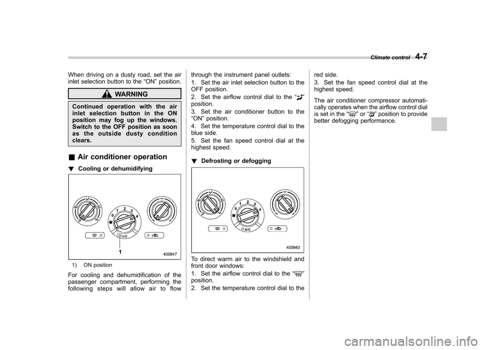
To direct warm air toward the floor:
1. Set the air inlet selection button to the
OFF position.
2. Set the airflow control dial to the “
”
position.
3. Set the temperature control dial to the
most comfortable level.
4. Set the fan speed control dial to the
desired speed. NOTE
Warm air also comes out from the right
and left air outlets. To stop warm
airflow from these outlets, turn the
corresponding thumb-wheel down. !
Bi-level heating
This setting allows you to direct air of
different temperatures from the instrument
panel and foot outlets. The air from the
foot outlets is slightly warmer than from
the instrument panel outlets.
1. Set the air inlet selection button to the
OFF position.
2. Set the airflow control dial to the “
”
position.
3. Set the temperature control dial to the
desired temperature level.
4. Set the fan speed control dial to the desired speed.
Setting the temperature control dial fully
turned to the red area or blue area
decreases the temperature difference
between the air from the instrument panel
outlets and the air from the foot outlets. !
Ventilation
To force outside air through the instrument
panel outlets:
1. Set the air inlet selection button to the
OFF position.
2. Set the airflow control dial to the “
”
position.
3. Set the temperature control dial all the
way left.
4. Set the fan speed control dial to the
desired speed.
Page 162 of 402

When driving on a dusty road, set the air
inlet selection button to the“ON ”position.
WARNING
Continued operation with the air
inletselectionbuttonintheON
position may fog up the windows.
Switch to the OFF position as soon
as the outside dusty conditionclears.
& Air conditioner operation
! Cooling or dehumidifying
1) ON position
For cooling and dehumidification of the
passenger compartment, performing the
following steps will allow air to flow through the instrument panel outlets:
1. Set the air inlet selection button to the
OFF position.
2. Set the airflow control dial to the
“
”
position.
3. Set the air conditioner button to the “ ON ”position.
4. Set the temperature control dial to the
blue side.
5. Set the fan speed control dial at the
highest speed. ! Defrosting or defogging
To direct warm air to the windshield and
front door windows:
1. Set the airflow control dial to the “
”
position.
2. Set the temperature control dial to the red side.
3. Set the fan speed control dial at the
highest speed.
The air conditioner compressor automati-
cally operates when the airflow control dial
is set in the
“
”or “”position to provide
better defogging performance. Climate control
4-7
Page 315 of 402

11-10Maintenance and service
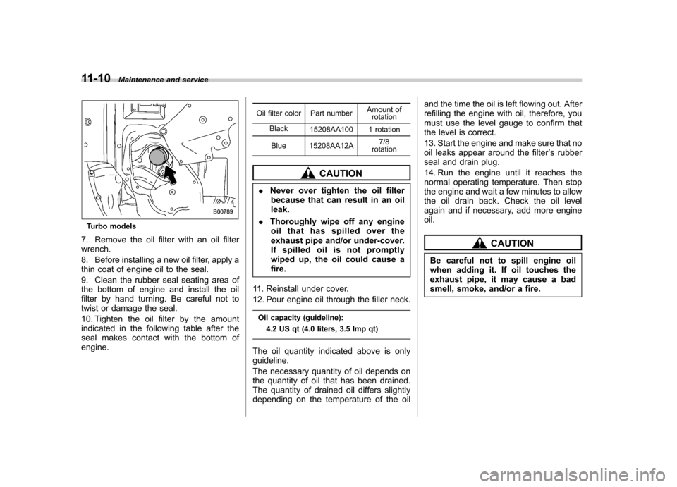
Turbo models
7. Remove the oil filter with an oil filter wrench.
8. Before installing a new oil filter, apply a
thin coat of engine oil to the seal.
9. Clean the rubber seal seating area of
the bottom of engine and install the oil
filter by hand turning. Be careful not to
twist or damage the seal.
10. Tighten the oil filter by the amount
indicated in the following table after the
seal makes contact with the bottom of engine. Oil filter color Part number
Amount of
rotation
Black 15208AA100 1 rotation
Blue 15208AA12A 7/8
rotation
CAUTION
. Never over tighten the oil filter
because that can result in an oil leak.
. Thoroughly wipe off any engine
oil that has spilled over the
exhaust pipe and/or under-cover.
If spilled oil is not promptly
wiped up, the oil could cause afire.
11. Reinstall under cover.
12. Pour engine oil through the filler neck. Oil capacity (guideline): 4.2 US qt (4.0 liters, 3.5 Imp qt)
The oil quantity indicated above is only guideline.
The necessary quantity of oil depends on
the quantity of oil that has been drained.
The quantity of drained oil differs slightly
depending on the temperature of the oil and the time the oil is left flowing out. After
refilling the engine with oil, therefore, you
must use the level gauge to confirm that
the level is correct.
13. Start the engine and make sure that no
oil leaks appear around the filter
’s rubber
seal and drain plug.
14. Run the engine until it reaches the
normal operating temperature. Then stop
the engine and wait a few minutes to allow
the oil drain back. Check the oil level
again and if necessary, add more engineoil.
CAUTION
Be careful not to spill engine oil
when adding it. If oil touches the
exhaust pipe, it may cause a bad
smell, smoke, and/or a fire.