Page 286 of 402
&Under the cargo area
1) Under-floor storage compartment (if
equipped) (Refer to “Under-floor storage
compartment ”F 6-16)
2) Jack handle
3) Tool bucket
4) Spare tire
1) Wheel nut wrench
2) Hex-head wrench (only models with moonroof)
3) Screwdriver
4) Jack
5) Towing hook (eye bolt)
The jack handle is stored under the cargo floor. The jack and towing hook are stored
in the tool bucket that is located in the
recess of the spare tire wheel.
Also, the tools in the tool bag can be
stored in the tool bucket as illustrated.
For how to use the jack, refer to
“Flat tires ”
F 9-6. In case of emergency
9-5
Page 293 of 402

9-12In case of emergency
Engine overheating
WARNING
Never attempt to remove the radia-
tor cap until the engine has been
shut off and has fully cooled down.
When the engine is hot, the coolant
is under pressure. Removing the
cap while the engine is still hot
could release a spray of boiling hot
coolant, which could burn you very
seriously.
If the engine overheats, safely pull off the
road and stop the vehicle in a safe place. & If steam is coming from the
engine compartment
Turn off the engine and get everyone
away from the vehicle until it cools down. & If no steam is coming from
the engine compartment
1. Keep the engine running at idling speed.
2. Open the hood to ventilate the engine compartment.
Confirm that the cooling fan is turning. If
the fan is not turning, immediately turn off the engine and contact your authorized
dealer for repair.
3. After the engine coolant temperature
has dropped, turn off the engine.
If the coolant temperature high warning
light illuminates, turn off the engine.
4. After the engine has fully cooled down,
check the coolant level in the reservetank.
If the coolant level is below the
“LOW ”
mark, add coolant up to the “FULL ”mark.
5. If there is no coolant in the reserve
tank, add coolant to the reserve tank.
Then remove the radiator cap and fill the
radiator with coolant.
If you remove the radiator cap from a hot
radiator, first wrap a thick cloth around the
radiator cap, then turn the cap counter-
clockwise slowly without pressing down
until it stops. Release the pressure from
the radiator. After the pressure has been
fully released, remove the cap by pressing
down and turning it. Towing
If towing is necessary, it is best done by
your SUBARU dealer or a commercial
towing service. Observe the following
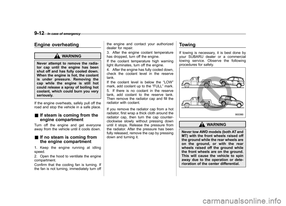
procedures for safety.
WARNING
Never tow AWD models (both AT and
MT) with the front wheels raised off
the ground while the rear wheels are
on the ground, or with the rear
wheels raised off the ground while
the front wheels are on the ground.
This will cause the vehicle to spin
away due to the operation or dete-
rioration of the center differential.
Page 294 of 402

&Towing and tie-down hooks
The towing hooks should be used only in
an emergency (e.g., to free a stuck vehicle
from mud, sand or snow).
CAUTION
. Use only the specified towing
hook and tie-down hook. Never
use suspension parts or other
parts of the body for towing or
tie-down purposes.
. To prevent deformation to the
front bumper and the towing
hook, do not apply excessive
lateral load to the towing hook.
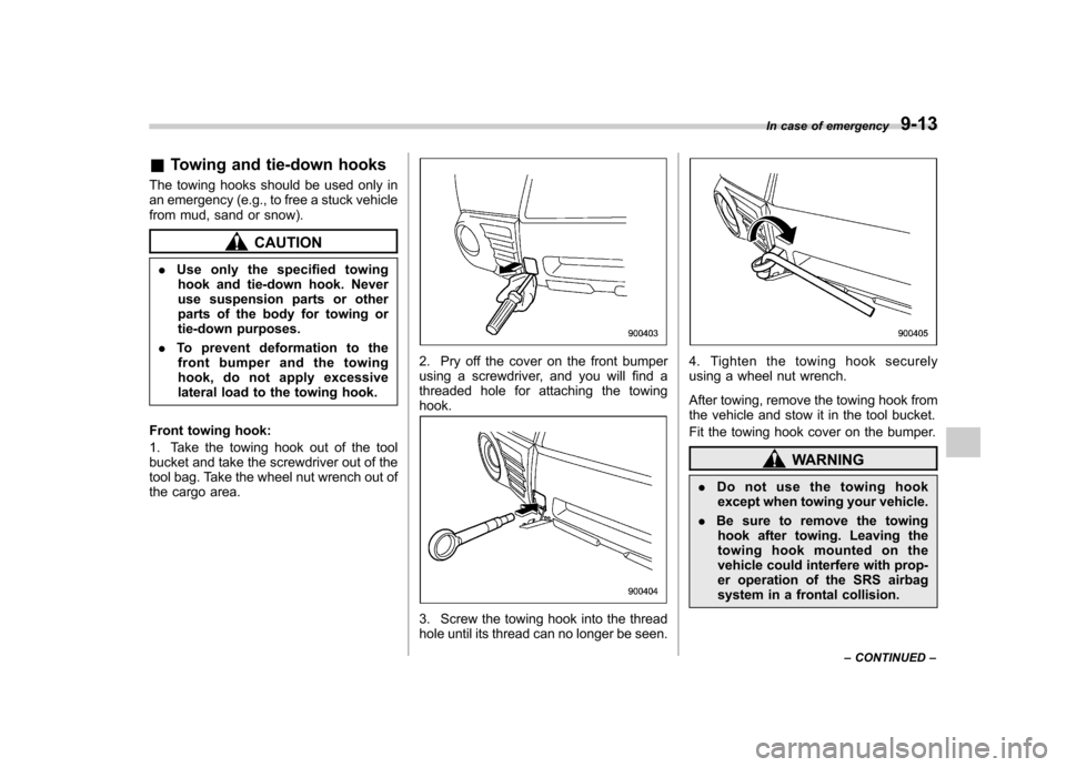
Front towing hook:
1. Take the towing hook out of the tool
bucket and take the screwdriver out of the
tool bag. Take the wheel nut wrench out of
the cargo area.
2. Pry off the cover on the front bumper
using a screwdriver, and you will find a
threaded hole for attaching the towinghook.
3. Screw the towing hook into the thread
hole until its thread can no longer be seen.
4. Tighten the towing hook securely
using a wheel nut wrench.
After towing, remove the towing hook from
the vehicle and stow it in the tool bucket.
Fit the towing hook cover on the bumper.
WARNING
. Do not use the towing hook
except when towing your vehicle.
. Be sure to remove the towing
hook after towing. Leaving the
towing hook mounted on the
vehicle could interfere with prop-
er operation of the SRS airbag
system in a frontal collision. In case of emergency
9-13
– CONTINUED –
Page 295 of 402

9-14In case of emergency
Rear towing hook:
CAUTION
If a trailer hitch is installed, it is not
possible to install the rear towinghook.
To install the rear towing hook, the
standard bumper beam must be
installed on the vehicle at a
SUBARU dealer. Consult a SUBARU
dealer for details.
Use a hitch ball and follow the
instructions below when towing. . The weight of the object being
towed must be less than the
weight of the vehicle.
. Drive the vehicle 20 mph (32
km/h) or less speed.
. Do not drive more than 31 miles
(50 km).
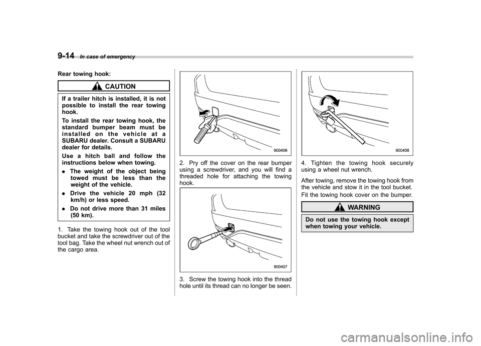
1. Take the towing hook out of the tool
bucket and take the screwdriver out of the
tool bag. Take the wheel nut wrench out of
the cargo area.
2. Pry off the cover on the rear bumper
using a screwdriver, and you will find a
threaded hole for attaching the towinghook.
3. Screw the towing hook into the thread
hole until its thread can no longer be seen.
4. Tighten the towing hook securely
using a wheel nut wrench.
After towing, remove the towing hook from
the vehicle and stow it in the tool bucket.
Fit the towing hook cover on the bumper.
WARNING
Do not use the towing hook except
when towing your vehicle.
Page 297 of 402

9-16In case of emergency
CAUTION
If your vehicle has a front under-
spoiler and rear underspoiler (if
equipped), be careful not to scrape
them when placing the vehicle on
the carrier and when removing the
vehicle from the carrier.
& Towing with all wheels on the ground
1. Release the parking brake and put the
transmission in neutral.
2. The ignition switch should be in the “Acc ”position while the vehicle is being
towed.
3. Take up slack in the towline slowly to
prevent damage to the vehicle.
WARNING
. Never turn the ignition switch to
the “LOCK ”position while the
vehicle is being towed because
the steering wheel and the direc-
tion of the wheels will be locked.
. Remember that the brake booster
and power steering do not func-
tion when the engine is not
running. Because the engine is
turned off, it will take greater
effort to operate the brake pedal
and steering wheel.
CAUTION
. If transmission failure occurs,
transport your vehicle on a flat-
bed truck.
. Do not run the engine while being
towed using this method. Trans-
mission damage could result if
the vehicle is towed with the
engine running.
. For models with automatic trans-
mission, the traveling speed
must be limited to less than 20
mph (30 km/h) and the traveling
distance to less than 31 miles (50
km). For greater speeds and distances, transport your vehicle
on a flat-bed truck.
Page 362 of 402
&Tires
Tire size P215/65R16 96H P225/55R17 95H
Wheel size 1666
1/2J1 66 61/2JJ 17 67JJ
Pressure Front 30 psi (210 kPa, 2.1 kgf/cm2) 32 psi (220 kPa, 2.2 kgf/cm2)
Rear 29 psi (200 kPa, 2.0 kgf/cm2) 30 psi (210 kPa, 2.1 kgf/cm2)
Rear when towing trailer 35 psi (240 kPa, 2.4 kgf/cm2) 36 psi (250 kPa, 2.5 kgf/cm2)
Temporary
spare tire Size
T155/70 D17
Pressure 60 psi (420 kPa, 4.2 kgf/cm
2)
NOTE
For the Latin American models, there is a conventional tire installed under the floor of the cargo area. & Wheel alignment
Toe Front 0+ 0.12 in (0 +3 mm), Toe angle (sum of both wheels): 0 8+0815 ’
Rear 0 +0.12 in (0 +3 mm), Toe angle (sum of both wheels): 0 8+0815 ’
Camber * Front 0800 ’+ 0845 ’
Rear 0
800 ’+ 0845 ’
*: The difference between right-hand camber and left-hand camber should be within 45 ’or less. Specifications
12-5
Page 376 of 402
&Recommended tire inflation pressure
! Recommended cold tire inflation pressure
Recommended cold tire inflation pressure for your vehicle ’s tires is as follows.
Tire size P215/65R16 96H P225/55R17 95H
Wheel size 16 66
1/2J1 66 61/2JJ 17 67JJ
Pressure Front 30 psi (210 kPa, 2.1 kgf/cm
2)32 psi
(220 kPa, 2.2 kgf/cm2)
Rear 29 psi (200 kPa, 2.0 kgf/cm
2) 30 psi
(210 kPa, 2.1 kgf/cm2)
Rear when towing trailer 35 psi (240 kPa, 2.4 kgf/cm
2) 36 psi
(250 kPa, 2.5 kgf/cm2)
Temporary
spare tire Size
T155/70 D17
Pressure 60 psi (420 kPa, 4.2 kgf/cm
2)
Consumer information and Reporting safety defects
13-5
– CONTINUED –
Page 382 of 402

&Tire care –maintenance and
safety practices
. Check on a daily basis that the
tires are free from serious damage,
nails, and stones. At the same time,
check the tires for abnormal wear. . Inspect the tire tread regularly
and replace the tires before their
tread wear indicators become visi-
ble. When a tire ’streadwear
indicator becomes visible, the tire
is worn beyond the acceptable limit
and must be replaced immediately.
With a tire in this condition, driving
at even low speeds in wet weather
can cause the vehicle to hydro-
plane. Possible resulting loss of
vehiclecontrolcanleadtoanaccident. . To maximize the life of each tire
and ensure that the tires wear
uniformly, it is best to rotate the
tires every 7,500 miles (12,000 km).
For information about the tire rota-
tion order, refer to “Tire rotation ”
F 11-35 .
Replace any damaged or un- evenly worn tires at the time of
rotation. After tire rotation, adjust
the tire pressures and make sure
the wheel nuts are correctly tigh-
tened. For information about the
tightening torque and tightening
sequence for the wheel nuts, refer to
“Flat tires ”F 9-6 .
& Vehicle load limit –how to
determine
The load capacity of your vehicle is
determined by weight, not by avail-
able cargo space. The load limit of
your vehicle is shown on the
vehicle placard attached to the
driver ’s side B-pillar. Locate the
statement “The combined weight
of occupants and cargo should
never exceed XXX kg or XXX lbs ”
on your vehicle ’s placard.
Thevehicleplacardalsoshows
seating capacity of your vehicle.
The total load capacity includes the
total weight of driver and all pas-
sengers and their belongings, any
cargo, any optional equipment such as a trailer hitch, roof rack or bike
carrier, etc., and the tongue load of
a trailer. Therefore cargo capacity
can be calculated by the followingmethod.
Cargo capacity = Load limit
�(total
weight of occupants + total weight
of optional equipment + tongue
load of a trailer (if applicable))
For information about vehicle load-
ing, refer to “Loading your vehicle ”
F 8-12 .
For information about towing capa-
city and weight limits, refer to“ Trailer towing ”F 8-18 .
! Calculating total and load ca-
pacities varying seating con-
figurations
Calculate the available load capa-
city as shown in the following examples:
Consumer information and Reporting safety defects
13-11
– CONTINUED –