2010 SUBARU FORESTER light
[x] Cancel search: lightPage 310 of 402
Engine hood
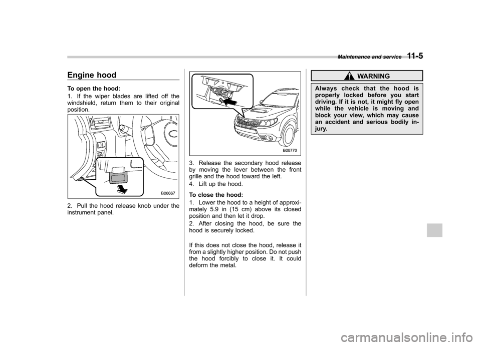
To open the hood:
1. If the wiper blades are lifted off the
windshield, return them to their originalposition.
2. Pull the hood release knob under the
instrument panel.
3. Release the secondary hood release
by moving the lever between the front
grille and the hood toward the left.
4. Lift up the hood.
To close the hood:
1. Lower the hood to a height of approxi-
mately 5.9 in (15 cm) above its closed
position and then let it drop.
2. After closing the hood, be sure the
hood is securely locked.
If this does not close the hood, release it
from a slightly higher position. Do not push
the hood forcibly to close it. It could
deform the metal.
WARNING
Always check that the hood is
properly locked before you start
driving. If it is not, it might fly open
while the vehicle is moving and
block your view, which may cause
an accident and serious bodily in-
jury. Maintenance and service
11-5
Page 315 of 402
11-10Maintenance and service
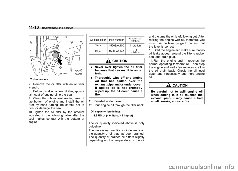
Turbo models
7. Remove the oil filter with an oil filter wrench.
8. Before installing a new oil filter, apply a
thin coat of engine oil to the seal.
9. Clean the rubber seal seating area of
the bottom of engine and install the oil
filter by hand turning. Be careful not to
twist or damage the seal.
10. Tighten the oil filter by the amount
indicated in the following table after the
seal makes contact with the bottom of engine. Oil filter color Part number
Amount of
rotation
Black 15208AA100 1 rotation
Blue 15208AA12A 7/8
rotation
CAUTION
. Never over tighten the oil filter
because that can result in an oil leak.
. Thoroughly wipe off any engine
oil that has spilled over the
exhaust pipe and/or under-cover.
If spilled oil is not promptly
wiped up, the oil could cause afire.
11. Reinstall under cover.
12. Pour engine oil through the filler neck. Oil capacity (guideline): 4.2 US qt (4.0 liters, 3.5 Imp qt)
The oil quantity indicated above is only guideline.
The necessary quantity of oil depends on
the quantity of oil that has been drained.
The quantity of drained oil differs slightly
depending on the temperature of the oil and the time the oil is left flowing out. After
refilling the engine with oil, therefore, you
must use the level gauge to confirm that
the level is correct.
13. Start the engine and make sure that no
oil leaks appear around the filter
’s rubber
seal and drain plug.
14. Run the engine until it reaches the
normal operating temperature. Then stop
the engine and wait a few minutes to allow
the oil drain back. Check the oil level
again and if necessary, add more engineoil.
CAUTION
Be careful not to spill engine oil
when adding it. If oil touches the
exhaust pipe, it may cause a bad
smell, smoke, and/or a fire.
Page 317 of 402
11-12Maintenance and service
&Recommended grade and
viscosity under severe driv-
ing conditions
If the vehicle is used in desert areas, in
areas with very high temperatures, or is
used for heavy-duty applications, use of
oil with the following grade and viscosities
is recommended.
API classification SM (or SL): SAE viscosity No.: 30, 40, 10W-50,
20W-40, 20W-50
& Synthetic oil
You can use synthetic engine oil that
meets the same requirements given for
conventional engine oil. When using
synthetic oil, you must use oil of the same
classification, viscosity and grade shown
in this Owner ’s Manual, and must follow
the oil and filter changing intervals shown
in the maintenance schedule. Cooling system
WARNING
Never attempt to remove the radia-
tor cap until the engine has been
shut off and has cooled down
completely. Since the coolant is
under pressure, you may suffer
serious burns from a spray of boil-
ing hot coolant when the cap isremoved.
CAUTION
. Vehicles are filled at the factory
with SUBARU Super Coolant that
does not require the first change
for 11 years/137,500 miles (11
years/220,000 km). This coolant
should not be mixed with any
other brand or type of coolant
during this period. Mixing with a
different coolant will reduce the
life of the coolant. Should it be
necessary to top up the coolant
for any reason, use only
SUBARU Super Coolant.
If the SUBARU Super Coolant is
diluted with another brand or
type, the maintenance interval is shortened to that of the mixingcoolant.
. Do not splash the engine coolant
over painted parts. The alcohol
contained in the engine coolant
may damage the paint surface.
& Cooling fan, hose and con- nections
Your vehicle employs an electric cooling
fan which is thermostatically controlled to
operate when the engine coolant reaches
a specific temperature.
If the radiator cooling fan does not operate
even when the coolant temperature high
warning light blinks or illuminates in RED,
the cooling fan circuit may be defective.
Refer to “Coolant temperature low indica-
tor light/Coolant temperature high warninglight ”F 3-13.
Check the fuse and replace it if necessary.
If the fuse is not blown, have the cooling
system checked by your SUBARU dealer.
Refer to “Fuses ”F 11-44 and “Fuse panel
located in the engine compartment ”F 12-
8.
If frequent addition of coolant is neces-
sary, there may be a leak in the engine
cooling system. It is recommended that
Page 331 of 402
11-26Maintenance and service
&Recommended clutch fluid
FMVSS No. 116, fresh DOT 3 or DOT 4
brake fluid
CAUTION
Never use different brands of clutch
fluid together. Also, avoid mixing
DOT 3 and DOT 4 brake fluids even if
they are the same brand. Brake booster
If the brake booster does not operate as
described in the following, have it checked
by your SUBARU dealer.
1. With the engine off, depress the brake
pedal several times, applying the same
pedal force each time. The distance the
pedal travels should not vary.
2. With the brake pedal depressed, start
the engine. The pedal should move
slightly down to the floor.
3. With the brake pedal depressed, stop
the engine and keep the pedal depressed
for 30 seconds. The pedal height should
not change.
4. Start the engine again and run for
approximately 1 minute then turn it off.
Depress the brake pedal several times to
check the brake booster. The brake
booster operates properly if the pedal
stroke decreases with each depression. NOTE
For models equipped with the brake
assist system, when you depress the
brake pedal strongly or suddenly, the
following phenomena occur. However,
even though these occur, they do not
indicate any malfunctions, and the
brake assist system is operating prop- erly. .
You might feel that the brake pedal
is applied by lighter force and gener-
ates a greater braking force.. You might hear clicking (knocking)
sounds around brake pedal.
Brake assist is not a system that brings
more braking ability to the vehicle
beyond its breaking capability.
Page 332 of 402
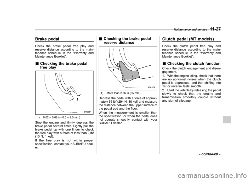
Brake pedal
Check the brake pedal free play and
reserve distance according to the main-
tenance schedule in the“Warranty and
Maintenance Booklet ”.
& Checking the brake pedal
free play
1) 0.02 –0.08 in (0.5 –2.0 mm)
Stop the engine and firmly depress the
brake pedal several times. Lightly pull the
brake pedal up with one finger to check
the free play with a force of less than 2 lbf
(10 N, 1 kgf).
If the free play is not within proper
specification, contact your SUBARU deal-
er. &
Checking the brake pedal
reserve distance
1) More than 2.56 in (65 mm)
Depress the pedal with a force of approxi-
mately 66 lbf (294 N, 30 kgf) and measure
the distance between the upper surface of
the pedal pad and the floor.
When the measurement is smaller than
the specification, or when the pedal does
not operate smoothly, contact with your
SUBARU dealer. Clutch pedal (MT models)
Check the clutch pedal free play and
reserve distance according to the main-
tenance schedule in the
“Warranty and
Maintenance Booklet ”.
& Checking the clutch function
Check the clutch engagement and disen-gagement.
1. With the engine idling, check that there
are no abnormal noises when the clutch
pedal is depressed, and that shifting into
1st or reverse feels smooth.
2. Start the vehicle by releasing the pedal
slowly to check that the engine and
transmission smoothly couple without
any sign of slippage. Maintenance and service
11-27
– CONTINUED –
Page 333 of 402
11-28Maintenance and service
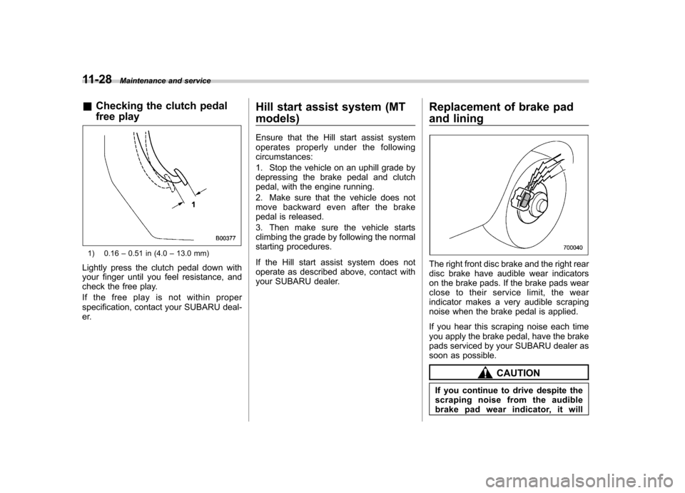
&Checking the clutch pedal
free play
1) 0.16 –0.51 in (4.0 –13.0 mm)
Lightly press the clutch pedal down with
your finger until you feel resistance, and
check the free play.
If the free play is not within proper
specification, contact your SUBARU deal-
er. Hill start assist system (MT models)
Ensure that the Hill start assist system
operates properly under the followingcircumstances:
1. Stop the vehicle on an uphill grade by
depressing the brake pedal and clutch
pedal, with the engine running.
2. Make sure that the vehicle does not
move backward even after the brake
pedal is released.
3. Then make sure the vehicle starts
climbing the grade by following the normal
starting procedures.
If the Hill start assist system does not
operate as described above, contact with
your SUBARU dealer.
Replacement of brake pad
and lining
The right front disc brake and the right rear
disc brake have audible wear indicators
on the brake pads. If the brake pads wear
close to their service limit, the wear
indicator makes a very audible scraping
noise when the brake pedal is applied.
If you hear this scraping noise each time
you apply the brake pedal, have the brake
pads serviced by your SUBARU dealer as
soon as possible.
CAUTION
If you continue to drive despite the
scraping noise from the audible
brake pad wear indicator, it will
Page 334 of 402
result in the need for costly brake
rotor repair or replacement.
& Breaking-in of new brake
pads and linings
When replacing the brake pad or lining,
use only genuine SUBARU parts. After
replacement, the new parts must be
broken in as follows. ! Brake pad and lining
While maintaining a speed of 30 to 40
mph (50 to 65 km/h), step on the brake
pedal lightly. Repeat this five or moretimes. ! Parking brake lining
1.Drivethevehicleataspeedof
approximately 22 mph (35 km/h).
2. With the parking brake release button
pushed in, pull the parking brake lever
SLOWLY and GENTLY (pulling with a
force of approximately 33 lbf [147 N, 15kgf]).
3. Drive the vehicle for approximately
220 yards (200 meters) in this condition.
4. Wait 5 to 10 minutes for the parking
brake to cool down. Repeat this proce-dure.
5. Check the parking brake stroke. If the
parking brake stroke is out of the specified range, adjust it by turning the adjusting nut
located on the parking brake lever.
Parking brake stroke: 7–8 notches / 45 lbf (200 N, 20.4 kgf)
WARNING
A safe location and situation should
be selected for break-in driving.
CAUTION
Pulling the parking brake lever too
forcefully may cause the rear
wheels to lock. To avoid this, be
certain to pull the lever up slowly
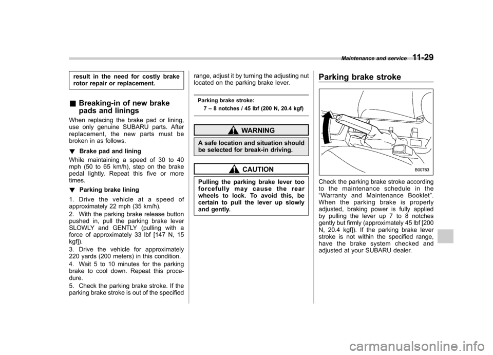
and gently. Parking brake stroke
Check the parking brake stroke according
to the maintenance schedule in the“
Warranty and Maintenance Booklet ”.
When the parking brake is properly
adjusted, braking power is fully applied
by pulling the lever up 7 to 8 notches
gently but firmly (approximately 45 lbf [200
N, 20.4 kgf]). If the parking brake lever
stroke is not within the specified range,
have the brake system checked and
adjusted at your SUBARU dealer. Maintenance and service
11-29
Page 335 of 402

11-30Maintenance and service
Tires and wheels &Types of tires
You should be familiar with type of tires
present on your vehicle.
The factory-fitted tires are all-season tires. ! All season tires
All season tires are designed to provide
an adequate measure of traction, handling
and braking performance in year-round
driving including snowy and icy road
conditions. However all season tires do
not offer as much traction performance as
winter (snow) tires in heavy or loose snow
or on icy roads.
All season tires are identified by “ALL
SEASON ”and/or “M+S ”(Mud & Snow) on
the tire sidewall. ! Summer tires
Summer tires are high-speed capability
tires best suited for highway driving under
dry conditions.
Summer tires are inadequate for driving
on slippery roads such as on snow-
covered or icy roads.
If you drive your vehicle on snow-covered
or icy roads, we strongly recommend the
use of winter (snow) tires.
When installing winter tires, be sure to
replace all four tires. !
Winter (snow) tires
Winter tires are best suited for driving on
snow-covered and icy roads. However
winter tires do not perform as well as
summer tires and all season tires on roads
other than snow-covered and icy roads.
& Tire pressure monitoring
system (TPMS) (U.S.-spec.models)
The tire pressure monitoring system pro-
vides the driver with a warning message
by sending a signal from a sensor that is
installed in each wheel when tire pressure
is severely low. The tire pressure monitor-
ing system will activate only when the
vehicle is driven. Also, this system may
not react immediately to a sudden drop in
tire pressure (for example, a blow-out
caused by running over a sharp object).
If you adjust the tire pressures in a warm
garage and will then drive the vehicle in
cold outside air, the resulting drop in tire
pressures may cause the low tire pressure
warning light to illuminate. To avoid this
problem when adjusting the tire pressures
in a warm garage, inflate the tires to
pressures higher than those shown on the
tire placard. Specifically, inflate them by an
extra 1 psi (6.9 kPa, 0.07 kgf/cm
2) for
every difference of 10 8F (5.6 8C) between the temperature in the garage and the
temperature outside. By way of example,
the following table shows the required tire
pressures that correspond to various out-
side temperatures when the temperature
in the garage is 60
8F (15.6 8C).
Example:
Tire size: P215/65R16 96H
Standard tire pressures:
Front: 30 psi (210 kPa, 2.1 kgf/cm
2)
Rear: 29 psi (200 kPa, 2.0 kgf/cm2)
Garage temperature: 60 8F (15.6 8C)
Outside
temperature Adjusted pressure
[psi (kPa, kgf/cm
2)]
front rear
30 8F( �18C) 33
(230, 2.3) 32
(220, 2.2)
10 8F( �12 8C) 35
(240, 2.4) 34
(235, 2.35)
� 10 8F( �23 8C) 37
(255, 2.55) 36
(250, 2.5)
Example:
Tire size: P225/55R17 95H
Standard tire pressures:
Front: 32 psi (220 kPa, 2.2 kgf/cm
2)
Rear: 30 psi (210 kPa, 2.1 kgf/cm2)
Garage temperature: 60 8F (15.6 8C)