2010 SUBARU FORESTER wheel
[x] Cancel search: wheelPage 362 of 402

&Tires
Tire size P215/65R16 96H P225/55R17 95H
Wheel size 1666
1/2J1 66 61/2JJ 17 67JJ
Pressure Front 30 psi (210 kPa, 2.1 kgf/cm2) 32 psi (220 kPa, 2.2 kgf/cm2)
Rear 29 psi (200 kPa, 2.0 kgf/cm2) 30 psi (210 kPa, 2.1 kgf/cm2)
Rear when towing trailer 35 psi (240 kPa, 2.4 kgf/cm2) 36 psi (250 kPa, 2.5 kgf/cm2)
Temporary
spare tire Size
T155/70 D17
Pressure 60 psi (420 kPa, 4.2 kgf/cm
2)
NOTE
For the Latin American models, there is a conventional tire installed under the floor of the cargo area. & Wheel alignment
Toe Front 0+ 0.12 in (0 +3 mm), Toe angle (sum of both wheels): 0 8+0815 ’
Rear 0 +0.12 in (0 +3 mm), Toe angle (sum of both wheels): 0 8+0815 ’
Camber * Front 0800 ’+ 0845 ’
Rear 0
800 ’+ 0845 ’
*: The difference between right-hand camber and left-hand camber should be within 45 ’or less. Specifications
12-5
Page 376 of 402

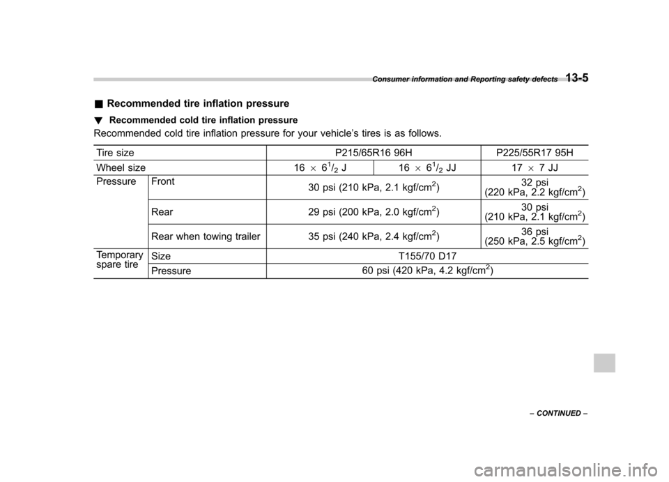
&Recommended tire inflation pressure
! Recommended cold tire inflation pressure
Recommended cold tire inflation pressure for your vehicle ’s tires is as follows.
Tire size P215/65R16 96H P225/55R17 95H
Wheel size 16 66
1/2J1 66 61/2JJ 17 67JJ
Pressure Front 30 psi (210 kPa, 2.1 kgf/cm
2)32 psi
(220 kPa, 2.2 kgf/cm2)
Rear 29 psi (200 kPa, 2.0 kgf/cm
2) 30 psi
(210 kPa, 2.1 kgf/cm2)
Rear when towing trailer 35 psi (240 kPa, 2.4 kgf/cm
2) 36 psi
(250 kPa, 2.5 kgf/cm2)
Temporary
spare tire Size
T155/70 D17
Pressure 60 psi (420 kPa, 4.2 kgf/cm
2)
Consumer information and Reporting safety defects
13-5
– CONTINUED –
Page 379 of 402

13-8Consumer information and Reporting safety defects
ing on a vehicle.
. Light truck (LT) tire
A tire designated by its manufac-
turer as primarily intended for use
on lightweight trucks or multipur-
pose passenger vehicles. . Load rating
The maximum load that a tire is
rated to carry for a given inflationpressure.. Maximum inflation pressure
The maximum cold inflation pres-
sure to which a tire may be inflated.. Maximum load rating
The load rating for a tire at the
maximum permissible inflation
pressure for that tire.. Maximum loaded vehicle weight
The sum of: (a) Curb weight
(b) Accessory weight
(c) Vehicle capacity weight
(d) Production options weight
. Maximum permissible inflation
pressure
The maximum cold inflation pres-
sure to which a tire may be inflated. .
Measuring rim
The rim on which a tire is fitted for
physical dimension requirements. . Normal occupant weight
150 lbs (68 kg) times the number of
occupants specified in the second
column of Table 1 that is appended
to the end of this section. . Occupant distribution
Distribution of occupants in a vehi-
cle as specified in the third column
of Table 1 that is appended to the
end of this section. . Open splice
Any parting at any junction of tread,
sidewall, or innerliner that extends
to cord material. . Outer diameter
The overall diameter of an inflated
new tire.. Overall width
The linear distance between the
exteriors of the sidewalls of an
inflated tire, including elevations
due to labeling, decorations, or
protective bands or ribs. .
Passenger car tire
A tire intended for use on passen-
ger cars, multipurpose passenger
vehicles, and trucks, that have a
gross vehicle weight rating (GVWR)
of 10,000 lbs (4,535 kg) or less. . Ply
A layer of rubber-coated parallel cords.. Ply separation
A parting of rubber compound
between adjacent plies.. Pneumatic tire
A mechanical device made of rub-
ber, chemicals, fabric and steel or
other materials, that, when
mounted on an automotive wheel,
provides the traction and contains
the gas or fluid that sustains theload. . Production options weight
The combined weight of those
installed regular production options
weighing over 5.1 lbs (2.3 kg) in
excess of those standard items
which they replace, not previously
considered in curb weight or acces-
Page 381 of 402

13-10Consumer information and Reporting safety defects
accessory weight, and normal oc-
cupant weight (distributed in accor-
dance with Table 1 that is ap-
pended to the end of this section)
and dividing by 2. .Wheel-holding fixture
The fixture used to hold the wheel
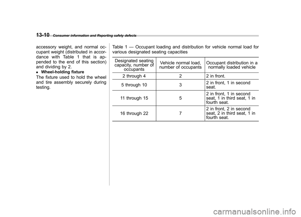
and tire assembly securely duringtesting. Table 1
—Occupant loading and distribution for vehicle normal load for
various designated seating capacities
Designated seating
capacity, number of
occupants Vehicle normal load,
number of occupants Occupant distribution in a
normally loaded vehicle
2 through 4 2 2 in front.
5 through 10 3 2 in front, 1 in second seat.
11 through 15 5 2 in front, 1 in second
seat, 1 in third seat, 1 in
fourth seat.
16 through 22 7 2 in front, 2 in second
seat, 2 in third seat, 1 in
fourth seat.
Page 382 of 402

&Tire care –maintenance and
safety practices
. Check on a daily basis that the
tires are free from serious damage,
nails, and stones. At the same time,
check the tires for abnormal wear. . Inspect the tire tread regularly
and replace the tires before their
tread wear indicators become visi-
ble. When a tire ’streadwear
indicator becomes visible, the tire
is worn beyond the acceptable limit
and must be replaced immediately.
With a tire in this condition, driving
at even low speeds in wet weather
can cause the vehicle to hydro-
plane. Possible resulting loss of
vehiclecontrolcanleadtoanaccident. . To maximize the life of each tire
and ensure that the tires wear
uniformly, it is best to rotate the
tires every 7,500 miles (12,000 km).
For information about the tire rota-
tion order, refer to “Tire rotation ”
F 11-35 .
Replace any damaged or un- evenly worn tires at the time of
rotation. After tire rotation, adjust
the tire pressures and make sure
the wheel nuts are correctly tigh-
tened. For information about the
tightening torque and tightening
sequence for the wheel nuts, refer to
“Flat tires ”F 9-6 .
& Vehicle load limit –how to
determine
The load capacity of your vehicle is
determined by weight, not by avail-
able cargo space. The load limit of
your vehicle is shown on the
vehicle placard attached to the
driver ’s side B-pillar. Locate the
statement “The combined weight
of occupants and cargo should
never exceed XXX kg or XXX lbs ”
on your vehicle ’s placard.
Thevehicleplacardalsoshows
seating capacity of your vehicle.
The total load capacity includes the
total weight of driver and all pas-
sengers and their belongings, any
cargo, any optional equipment such as a trailer hitch, roof rack or bike
carrier, etc., and the tongue load of
a trailer. Therefore cargo capacity
can be calculated by the followingmethod.
Cargo capacity = Load limit
�(total
weight of occupants + total weight
of optional equipment + tongue
load of a trailer (if applicable))
For information about vehicle load-
ing, refer to “Loading your vehicle ”
F 8-12 .
For information about towing capa-
city and weight limits, refer to“ Trailer towing ”F 8-18 .
! Calculating total and load ca-
pacities varying seating con-
figurations
Calculate the available load capa-
city as shown in the following examples:
Consumer information and Reporting safety defects
13-11
– CONTINUED –
Page 387 of 402

13-16Consumer information and Reporting safety defects
form to Federal Safety Require-
ments in addition to these grades. &Treadwear
The treadwear grade is a compara-
tive rating based on the wear rate of
the tire when tested under con-
trolled conditions on a specified
government test course.
For example, a tire graded 150
would wear one and one-half (1-
1/2) times as well on the govern-
ment course as a tire graded 100.
The relative performance of tires
depends upon the actual conditions
of their use, however, and may
depart significantly from the norm
due to variations in driving habits,
service practices and differences in
road characteristics and climate. & Traction AA, A, B, C
The traction grades, from highest to
lowest, are AA, A, B and C. Those
grades represent the tire ’s ability to
stop on wet pavement as measured
under controlled conditions on spe- cified government test surfaces of
asphalt and concrete. A tire marked
C may have poor traction perfor- mance.
WARNING
The traction grade assigned to
this tire is based on straight-
ahead braking traction tests,
and does not include accel-
eration, cornering, hydroplan-
ing, or peak traction charac-teristics.
& Temperature A, B, C
The temperature grades are A (the
highest), B, and C, representing thetire ’s resistance to the generation of
heat and its ability to dissipate heat
when tested under controlled con-
ditions on a specified indoor labora-
tory test wheel. Sustained high
temperature can cause the material
of the tire to degenerate and reduce
tire life, and excessive temperature
can lead to sudden tire failure. The grade C corresponds to a level of
performance which all passenger
car tires must meet under the
Federal Motor Vehicle Safety Stan-
dards No. 109. Grades B and A
represent higher levels of perfor-
mance on the laboratory test wheel
than the minimum required by law.
WARNING
The temperature grade for this
tire is established for a tire
that is properly inflated and
not overloaded. Excessive
speed, underinflation, or ex-
cessive loading, either sepa-
rately or in combination, can
cause heat buildup and possi-
ble tire failure.
Page 391 of 402

14-2Index
A
ABS (Anti-lock Brake System) ..................................... 7-23
Warning light ................................................. 3-16, 7-23
Accessories ....................................................... 5-4, 11-46
Accessory power outlet ................................................. 6-9
Active head restraint ..................................................... 1-5
Air cleaner element ................................................... 11-15
Air conditioner Automatic climate control system ............................. 4-10
Manual climate control system ................................... 4-7
Air filtration system ..................................................... 4-13
Airflow selection Automatic climate control system ......................... 4-2, 4-9
Manual climate control system ............................. 4-2, 4-4
Alarm system ............................................................ 2-14
All-Wheel Drive warning light ....................................... 3-18
Aluminum wheel ....................................................... 11-37
Cleaning ............................................................... 10-3
Antenna system ........................................................... 5-2
Anti-lock Brake System (ABS) ..................................... 7-23
Arming the system ..................................................... 2-15
Armrest ....................................................................... 1-7
Ashtray ..................................................................... 6-11
AT OIL TEMP warning light ......................................... 3-14
Audio Antenna system ....................................................... 5-2
Auxiliary input jack ................................................. 5-25
CD player operation ............................................... 5-17
Control button ........................................................ 5-28
FM/AM radio operation ........................................... 5-10
Power and sound controls ......................................... 5-7 Satellite radio operations
......................................... 5-13
Set ........................................................................ 5-4XM
TMsatellite radio reception ................................... 5-2
Auto-dimming mirror/compass .............................. 3-32, 3-34
Automatic climate control system ................................... 4-8
Automatic headlight beam leveler ................................. 3-27
Warning light .......................................................... 3-18
Automatic transmission ............................................... 7-15
Capacities ............................................................. 12-4
Fluid ................................................................... 11-20
MANUAL mode ...................................................... 7-19
Oil temperature warning light (AT OIL TEMP) ............. 3-14
Select lever ........................................................... 7-16
Shift lock function ................................................... 7-17
Shift lock release .................................................... 7-17
SPORT mode ........................................................ 7-20
Automatic/Emergency Locking Retractor (A/ELR) ........... 1-12
Auxiliary input jack ...................................................... 5-25
BBattery .................................................................... 11-43
Drainage prevention function ..................................... 2-5
Jump starting ......................................................... 9-10
Replacement (remote engine start transmitter) ........... 7-12
Replacement (remote keyless entry system) .............. 2-10
Booster seat .............................................................. 1-29
Bottle holder ............................................................... 6-9
Brake
Assist .................................................................... 7-22
Booster ....................................................... 7-22, 11-26
Fluid ................................................................... 11-24
Page 392 of 402

Pad and lining...................................................... 11-29
Parking ........................................................ 7-31, 11-29
Pedal .................................................................. 11-27
System ................................................................. 7-22
Brake pedal Free play ............................................................. 11-27
Reserve distance .................................................. 11-27
Brake system ............................................................ 7-22
Warning light ......................................................... 3-17
Braking ..................................................................... 7-21
Tips...................................................................... 7-21
Breaking-in of new brake pads and linings ................... 11-29
Bulb
Chart .................................................................. 12-10
Replacing ............................................................. 11-46
C Capacities ................................................................. 12-4
Cargo area
Cover ................................................................... 6-13
Light ............................................................. 6-3, 11-50
Tie-down hooks ..................................................... 6-15
Cargo tray ................................................................. 10-6
Catalytic converter ....................................................... 8-3
Center Console .................................................................. 6-5
Ventilators ............................................................... 4-3
Center and side ventilators ............................................ 4-3
Changing Coolant ................................................................ 11-13
Flat tire ................................................................... 9-6 Oil and oil filter
....................................................... 11-9
Charge warning light ................................................... 3-14
CHECK ENGINE warning light/Malfunction indicator lamp ...................................................................... 3-12
Checking Brake pedal free play ............................................ 11-27
Brake pedal reserve distance ................................. 11-27
Clutch function ..................................................... 11-27
Clutch pedal free play ........................................... 11-28
Coolant level ........................................................ 11-13
Fluid level (automatic transmission fluid) .................. 11-20
Fluid level (brake fluid) .......................................... 11-24
Fluid level (clutch fluid) .......................................... 11-25
Fluid level (power steering fluid) .. ........................... 11-23
Fluid level (washer fluid) ........................................ 11-38
Oil level (engine oil) ................................................ 11-8
Oil level (front differential gear oil) .......................... 11-21
Oil level (manual transmission oil) .......................... 11-19
Child restraint systems ................................................ 1-23
Installation of a booster seat .................................... 1-29
Installation with A/ELR seatbelt ... ............................. 1-26
Lower and tether anchorages ................................... 1-30
Top tether anchorages ............................................ 1-33
Child safety ................................................................... 5
Locks .................................................................... 2-19
Chime Key........................................................................ 3-5 Light ..................................................................... 3-25
Seatbelt. ........................................................ 1-13, 3-10
Cleaning Aluminum wheels ................................................... 10-3 Index
14-3