Page 1 of 18
ŠkodaYETI
SUPPLEMENT TO THE OWNER'S MANUAL
Technical Changes 11/2010
Dodatek Návodu k obsluze
Yeti anglicky 11.10
S90.5612.08.20
5L0 012 025 GP
SIMPLY CLEVER
Page 2 of 18

Introduction1
IntroductionThis supplement replaces the Owner's manual YETI Edition 05.10 referred to in the
following as the Owner's manual.
The information given in this supplement takes preference over the information in the
Owner's manual.
Special equipment is marked with the symbol *.
We wish you a good journey
Škoda Auto a.s.Fuel gaugeThe fuel tank has a capacity of about 55 litres or 60 litres
1).
Multi-functional indicator (onboard computer)*Multi-functional indicator (onboard comput er) is only available as a special equip-
ment item.Safelock
Note
When activating the Safelock function after you lock the vehicle, the message CHECK
SAFELOCK will appear in the display of the inst rument cluster. In vehicles equipped
with a MAXIDOT info display*, the message Check deadlock! Owner's manual!
(Observe SAFE locking! Car documentation!) appears.
Rear seatsThe seat rests of the rear outer seats are not fitted with a guide loop of the seat belt.
If the seat belts are not in use, they can be fixed into place by pushing them through
the opening next to the seat in the direction of arrow fig. 1 .Seat heaters*If you regulate the rear seat heating at full power - level 3, this will automatically switch
back to level 2 after 10 minutes (2 wa rning lights in the switch light up).DVD pre-installation*Fig. 2 Seat backrest - left front seat/right front seat
1)Ye t i 4 x 4
Fig. 1 Fastening the seat belt
s35k.9.book Page 1 Thursday, September 16, 2010 10:24 AM
Page 3 of 18

“START - STOP”*
2
Description
Openings for attachment of DVD player holder.
Audio input
Input, power supply for DVD player
Only a DVD pre-installation comes factory-fitted . It is located in the seat backrests of
the front seats.
The DVD player holder and DVD player can be purchased from the range of the Škoda
original accessories. Please also refer to the operating instructions of the DVD player
holder and DVD player.
WARNING
•
If the rear seats are occu pied, the DVD player holder must not be set up
alone (without DVD player) - risk of injury!
•
Do not use the DVD player holder when the rear seat backrests or the rear
seat are folded forwarded or have been removed completely. Note
Please pay attention to the information in the fitting instructions for the DVD player
holder/DVD player.“START - STOP”*
The “START-STOP” system helps you to save fuel while at the same time reducing
harmful exhaust emissions and CO
2 emissions.
The function is automatically activated ea ch time the ignition is switched on.
In the start-stop mode, the engine automatica lly switches to the vehicle's idle phase,
e.g. when stopped at traffic lights.
Information regarding the current state of the “START-STOP” system is indicated in the
display of the instrument cluster.
Automatic engine shut down (stop phase)– Stop the vehicle (where necessary, apply the handbrake).
– Take the vehicle out of gear.
– Take your foot off the clutch.Automatic engine restart (start phase).– Push down on the clutch.Switching the “START-STOP” system on and offYou can switch the “START STOP” syst em on/off by pressing the button fig. 3 .
When start-stop mode is deactivated, th e warning light in the button lights up.
If the vehicle is in the stop phase when manually switching off the system, the engine
starts automatically.
The “START-STOP” system is very complex. Some of the procedures are hard to check
without servicing. The general conditions for the proper functioning of the “START-
STOP” system are listed in the following overview.
Conditions for the automatic en gine shut down (stop phase)
AAABAC
Fig. 3 Dash panel: START-STOP System
button
The gearshift lever is in Neutral.The clutch pedal is not pressed!The driver has fastened the seat belt.The driver's door is closed.
s35k.9.book Page 2 Thursday, September 16, 2010 10:24 AM
Page 4 of 18
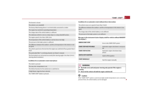
 Conditions for an automatic restart without driver intervention
Messages in the instrument cluster display (valid for vehicles wi")
“START - STOP”*3
Conditions for an automatic restart (start phase) Conditions for an automatic restart without driver intervention
Messages in the instrument cluster display (valid for vehicles without MAXIDOT
info display*)
WARNING
•
The brake servo unit and power steering only operate if the engine is
running.
•
Never let the vehicle roll with the engine switched off.Caution
If the “START-STOP” system is used at very high outside temperatures over a very long
period of time, the vehicle battery can be damaged.
The bonnet is closed.The vehicle is at a standstill.The factory-fitted towing device is no t electrically connected to a trailer.The engine has reached its operating temperature.The charge state of the vehicle battery is sufficient.The stationary vehicle is not on a steep slope or a steep downhill section.The engine speed is less than 1200 1/min.The temperature of the vehicle batte ry is not too low or too high.The pressure in the brake system is sufficient.The difference between the outdoor- and th e set temperature in the interior is not
too great.The vehicle speed since the last time the engine was switched off was greater than 3
km/h.The particulate filter* is not be ing cleaned, see Owner's manual.The front wheels are not turned excessively (t he steering angle is less than 3/4 of a
steering wheel revolution).The clutch is pressed.The max./min. temperature is set.The Defrost function for the windscreen is switched on.A high blower stage has been selected.The “START STOP” button is pressed.
The vehicle moves at a speed of more than 3 km/h.The difference between the outdoor- and the set temperature in the interior is too
great.The charge state of the vehicle battery is not sufficient.The pressure in the brake system is not sufficient.ERROR START STOP
Error in the START-STOP system
START STOP NOT POSSIBLE
Automatic engine shut down is not possi-
ble
START STOP ACTIVE
Automatic engine shut down (stop
phase)
SWITCH OFF IGNITION
Switch off the ignition
START MANUALLY
Start the engine manually
s35k.9.book Page 3 Thursday, September 16, 2010 10:24 AM
Page 5 of 18

Charging the vehicle battery
4Note
•
Changes to the outdoor temperature can have an effect on the internal tempera-
ture of the vehicle battery even after severa l hours. If the vehicle remains outdoors for
a long time in minus temperatures or in dire ct sunlight, it can take several hours until
the internal temperature of the vehicle battery reaches a suitable temperature for
proper operation of the “START STOP” system.
•
In some instances it may be necessary to start the engine manually with the igni-
tion key (e.g. when the seat belt is not inserted or the driver's door is opened for more
than 30 seconds). Follow the messages in the display of the instrument cluster.
•
If the air conditioning Clim atronic* is running in automatic mode, under certain
conditions, the engine may not switch off automatically.
Charging the vehicle battery
Caution
On vehicles with the “START/STOP” system, the negative cable of the charger must not
be connected directly to the negative pole of the vehicle battery, but only to the engine
earth fig. 4.Jump-starting on vehicles with the “START-STOP” system
On vehicles with the “START/STOP” system, the negative cable of the charger must not
be connected directly to the negative pole of the vehicle battery, but only to the engine
earth fig. 4 .Climatic *Using the systemThe set temperature will not be maintained automatically.
Fig. 4 Jump-starting on vehicles with
the START-STOP system
s35k.9.book Page 4 Thursday, September 16, 2010 10:24 AM
Page 6 of 18
Climatic *5
Climatic SettingFig. 5 Climatic: Control elementsRecommended settings for the Climatic control elements:
adjusting
Switch positions
Button
Air outlet vents 4
Defrost function, windscreen and
side windows
To the right up to the
stop
3
Switched off
Do not switch on
Open and adjust the flow of
air in direction of the side win-
dow
Anti-fog function, windscreen
and side windows
Desired tempera-ture
2
Activated
Do not switch on
Open and adjust the flow of
air in direction of the side win- dow
Quickest-possible heating
To the right up to the
stop
3
Switched off
briefly switched on
Opening
Comfort temperature
Desired tempera-ture
2 or 3
Switched off
Do not switch on
Opening
AA
AB
AC
A1
A4
s35k.9.book Page 5 Thursday, September 16, 2010 10:24 AM
Page 7 of 18
 RON
Use unleaded petrol 98 RON. You can also use unleaded RON 95. However some loss
of power is to be expected when doin")
Grades of petrol
6
Grades of petrolPrescribed fuel - unleaded petrol 98/(95) RON
Use unleaded petrol 98 RON. You can also use unleaded RON 95. However some loss
of power is to be expected when doing so.
If unleaded RON 98 or RON 95 is not available, you can refuel with unleaded RON 91
in an emergency. After refuelling, conti nue driving at medium engine speeds and
minimum engine load. Driving at high engine speeds or heavy engine loads can lead
to serious engine damage! Refuel with petr ol with the specified octane number as
often as possible.
Fuel with a lower octane number than RON 91 must not be used even in an emer-
gency. Otherwise you can ca use serious engine damage!RefuellingThe air relief valve in the filler tube of the fuel tank not part of the equipment installed
in the vehicle.
Vehicle tool kitFig. 6 Luggage compartment: Example for placing the vehicle tool kitThe vehicle tool kit also contains a tyre repair kit*(depending on equipment fitted).Tyre repair kit*General informationThe tyre repair kit is located in a box und er the carpet in the luggage compartment.
Use the tyre repair kit to reliably repair tyre damage caused by foreign bodies or a
puncture with diameters up to 4 mm. Do no t remove foreign bodies, e.g. screws or
nails, from the tyre!
Quickest-possible cooling
To the left up to the
stop
briefly 4, then 2 or 3
Activated
briefly switched on
Opening
optimal cooling
Desired tempera-ture
1, 2 or 3
Activated
Do not switch on
Open and adjust the flow of
air in direction of the vehicle roof
Fresh air mode - ventilation
To the left up to the
stop
required position:
Switched off
Do not switch on
Opening
adjusting
Switch positions
Button
Air outlet vents 4
AA
AB
AC
A1
A4
s35k.9.book Page 6 Thursday, September 16, 2010 10:24 AM
Page 8 of 18

Tyre repair kit*7
The repair can be undertaken on the vehicle immediately.
The repair with the tyre repair kit is not at all intended to replace a permanent repair
on the tyre, this repair only serves to reach the next specialist garage.
Do not use the tyre repair kit:•
to repair wheel damage,
•
in outside temperatures of less than -20 °C (-4 °F),
•
with tears or punctures greater than 4 mm in size,
•
to repair damage to the tyre wall,
•
when driving with very low tyre pressure or with a completely flat tyre,
•
if the use-by-date (see infl ation bottle) has passed.
WARNING
•
If you find yourself in flowing traffic switch on the hazard warning lights
system and place the warning triangle on the side of the road at the prescribed
distance from your vehicle. Comply with the national legal regulations. In this
way you are protecting not only yourself but also other road users.
•
Park the vehicle as far away as possible from the traffic flow. Park on as flat
and firm a surface as possible.
•
A tyre filled with sealant has the same driving characteristics as a standard
tyre.
•
Do not drive faster than 80 km/h, (50 mph).
•
Avoid accelerating at full throttle , sharp braking and fast cornering.
•
Check the tyre inflation pressure after driving 10 minutes.
•
Sealant is hazardous to heath. Remove immediately if it comes into contact
with the skin.For the sake of the environment
Used or aged sealing agent must be dispos ed of in accordance with environmental
protection regulations.
Note
•
Observe the manufacturer's usage instructions for the tyre repair kit.
•
You can purchase a new bottle of sealan t from the range of the Škoda original
accessories.
•
Change the wheel that was repaired using the tyre repair kit or consult a specialist
garage about possibilities for getting repairs done.
Components of the tyre repair kitFig. 7 Components of the tyre repair kitThe tyre repair kit is made up of the following parts:
Valve remover
Sticker with speed designation “max. 80 km/h”/“max. 50 mph”
Inflation hose with plug
Compressor
Tyre inflation hose
Tyre inflation pressure indicator
Air release valve
ON and OFF switch
12 volt cable connectorA1A2A3A4A5A6A7A8A9
s35k.9.book Page 7 Thursday, September 16, 2010 10:24 AM