2010 SKODA ROOMSTER brake
[x] Cancel search: brakePage 169 of 231

Inspecting and replenishing
168
If the fluid level has dropped below the MIN marking, do not drive any
further - risk of accident! Obtain professional assistance.
Replacing brake fluidBrake fluid absorbs moisture. This causes the fluid to absorb moisture from the
surrounding air over a period of time. Excessive water in the brake fluid may be the
cause of corrosion in the brake system. The water content also lowers the boiling point
of the brake fluid. This is why brake fluid must be replaced every two years.
One may only use new brake fluid approved by Škoda Auto. The brake fluid must
comply with one of the following standards or specifications:
VW 501 14,
FMVSS 116 DOT4,
DIN ISO 4925 CLASS 4.
We recommend that you have the brake fluid replaced by an authorised Škoda
Service Partner as part of an Inspection Service.
WARNING
Using old brake fluid can result in severe stress on the brakes because of the
formation of vapour bubbles in the br ake system. This greatly impairs the
braking efficiency and thus also the safety of your vehicle.
Brake fluid is toxic! It must therefor e be kept safely in closed original
containers and well away from children and unauthorized persons.Caution
Brake fluid damages the paintwork of the vehicle.
For the sake of the environment
In view of the problems involved with proper disposal of brake fluid, the special tools
and the professional knowledge required, we recommend you have the brake fluid
replaced by a specialist garage.
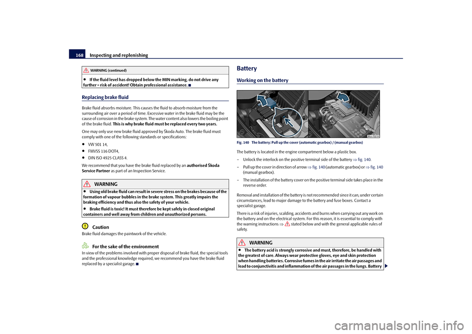
BatteryWorking on the batteryFig. 140 The battery: Pull up the cove r (automatic gearbox) / (manual gearbox)The battery is located in the engine compartment below a plastic box.
– Unlock the interlock on the positive terminal side of the battery fig. 140 .
– Pull up the cover in direction of arrow fig. 140 (automatic gearbox) or fig. 140
(manual gearbox).
– The installation of the battery cover on th e positive terminal side takes place in the
reverse order.
Removal and installation of the battery is not recommended since it can, under certain
circumstances, lead to ma jor damage to the battery and fuse boxes. Contact a
specialist garage.
There is a risk of injuries, scalding, accidents and burns when carrying out any work on
the battery and on the electrical system. For th is reason, it is essential to comply with
the warning instructions stated below and with the general applicable rules of
safety.
WARNING
The battery acid is strongly corrosive and must, therefore, be handled with
the greatest of care. Always wear prot ective gloves, eye and skin protection
when handling batteries. Corrosive fumes in the air irritate the air passages and
lead to conjunctivitis and inflammation of the air passages in the lungs. Battery
WARNING (continued)
s16g.4.book Page 168 Wednesday, February 10, 2010 3:53 PM
Page 177 of 231

Wheels and Tyres
176
The date of manufacture is also stated on the tyre wall (possibly only on the inside of
wheel).
DOT ... 13 10...
means, for example, that the tyre was ma nufactured in the 13th week of the year 2010.
Any spare wheel which differs from the tyres fitted to the vehicle (e.g. winter tyres or
low-profile tyres) should only be used for a short time in the event of a puncture and
when adopting an appropriately cautious styl e of driving. It should be replaced as
quickly as possible by a normal wheel.
WARNING
Only use those tyres or wheel rims which have been approved for your
model of Škoda Auto vehicle. Failure to observe this instruction will adversely
affect the road safety of your vehicle - risk of accident! Approval and licencing
of your vehicle on public roads ma y also become void as a result.
You must on no account drive at a high er speed than is permissible for your
tyres - risk of an accident resulting from tyre damage and loss of control over
your vehicle.
Tyres which are 6 years old or more should only be fitted in exceptional
cases and when adopting an approp riately cautious style of driving.
Never fit tyres which have already been used without having adequate
knowledge of their previous history. Tyre s age even if they have not been used
at all or only very little. A spare tyre must only be used in exceptional cases and
only then when adopting an appropriately cautious style of driving.
Do not, where possible, replace individu al tyres but at least replace them on
both wheels of a given axle at the same time. Always fit the tyres with the
deeper tread depth to the front wheels.
For the sake of the environment
Old tyres must be disposed of in conformity with the appropriate regulations.
Note
It is not normally possible to fit wheels from other models of cars for technical reasons.
This may also apply in certain circumstance s to the wheels of the same type of
vehicle.Wheel boltsWheels and wheel bolts are matched to each other in terms of design. Each time you
fit other wheels - e.g. light alloy wheels or wheels with winter tyres - you must therefore
also use the matching wheel bolts of the corr ect length and shape of spherical cap. This
is essential to ensure that the wheels are tightly fitted and that the brake system oper-
ates properly.
If you retrofit wheel trims (or have this done), please also ensure that an adequate
flow of air remains assured for cooling the brake system.
The specialist garages are informed about the technical possibilities which exist
regarding converting or retrofitting wheels, tyres and wheel trims.
WARNING
In case of incorrect treatment of the wheel bolts, the wheel can loosen when
the car is moving - risk of accident!
The wheel bolts must be clean and must turn easily. However, they must
never be treated with grease or oil.
If the wheel bolts are tightened to a too low tightening torque, the rim can
lossen when the car is moving - risk of accident! A tightening torque which is
too high can damage the bolts and threads and this can result in permanent
deformation of the contact surfaces on the rims.Caution
The prescribed tightening torque of the wheel bolts for steel and light alloy wheels is
120 Nm.
H
210 km/h
V
240 km/h
W
270 km/h
Speed symbol
Permissible maximum speed
s16g.4.book Page 176 Wednesda y, February 10, 2010 3:53 PM
Page 184 of 231

Breakdown assistance183
Using the system
Safety
Driving Tips
General Maintenance
Breakdown assistance
Praktik
Technical Data
Changing a wheelPreliminary workThe following steps should be carried ou t before actually changing the wheel.
– If it is necessary to change a wheel, park the vehicle as far away as possible from
the traffic flow. The place you choose should be level.
– Have all the occupants get out. While changing a wheel, the occupants of the
vehicle should not stand on the road (e.g. behind a crash barrier).
– Apply the handbrake firmly.
–Engage 1st gear or if your vehicle is fitted with an automatic gearbox, position the
selector lever into position P .
– If a trailer is coupled, uncouple it.
– Take the vehicle tool kit and the spare wheel page 181 out of the luggage
compartment.
WARNING
If you find yourself in flowing traffic switch on the hazard warning lights
system and place the warning triangle on the side of the road at the prescribed
distance from your vehicle while observing all national legal provisions. In this
way you are protecting not only yourself but also other road users.
Never start the engine with the vehicle si tting on the raised jack - danger of
suffering injury.Caution
If you have to change a wheel on a slope first block the opposite wheel with a stone or
similar object in order to secure the vehicle from unexpectedly rolling away.
Note
Comply with the national legal regulations.
Always change a wheel on a level surface as far as possible.
– Take off the full wheel trim* page 184 or the caps page 184.
– Slacken the wheel bolts page 185.
– Jack up the vehicle until the wheel to be changed is clear of the ground
page 185.
– Unscrew the wheel bolts and place them on a clean surface (cloth, paper etc.).
– Take off the wheel.
– Fit on the spare wheel* and tighten the wheel bolts slightly.
– Lower the car.
– Tighten the wheel bolts firmly, alternatel y and diagonally using the wrench (cross-
wise) page 185.
– Mount the full wheel trim/wheel trim cap or the caps.
Note
All bolts must be clean and must turn easily.
You must never grease or oil the wheel bolts!
When fitting on unidirectiona l tyres, ensure that the tyres rotate in the correct
direction page 173.
Subsequent stepsAfter changing the wheel, you mu st perform the following steps.
– Stow the vehicle tool kit in the space provided.
– Stow the replaced wheel in the luggage compartment.
– Check the tyre pressure on the spare wheel just mounted as soon as possible.
– Have the tightening torque of the wheel bolts checked with a torque wrench as
soon as possible. Steel and light alloy wheels must be tightened to a tightening
torque of 120 Nm.
s16g.4.book Page 183 Wednesda y, February 10, 2010 3:53 PM
Page 189 of 231

Breakdown assistance
188WARNING
The non-insulated parts of the terminal clamps must never make contact
with each other. Furthermore, the cable connected to the positive terminal of
the battery must not come into contact with electrically conducting parts of the
vehicle - risk of a short circuit!
Do not affix the jump starting cables to the negative terminal of the
discharged battery. There is the risk of detonating gas seeping out the battery
being ignited by the strong spark which results from the engine being started.
Do not affix the cable end to parts of the fuel and brake system.
Run the jump-start cables so that they cannot be caught by any rotating
parts in the engine compartment.
Do not bend over the batteries - risk of caustic burns!
The vent screws of the battery cells must be tightened firmly.
Keep any sources of ignition (naked flame, smouldering cigarettes etc.)
away from the battery - risk of an explosion!
Never jump-start the batteries which have a too low electrolyte level - risk
of explosion and caustic burns!
Tow-starting and towing vehicleGeneralPlease pay attention to the following instru ctions if you are going to use a tow rope:Driver of the towing vehicle– Do not drive off until the tow rope is taught.
– Release the clutch particularly gently when starting off.Driver of the towed vehicle– Switch the ignition on so that the steering wheel is not blocked and you can also operate the turn signal lights, the headlight flasher, the windscreen wipers and
windscreen washer system. – Take the vehicle out of gear or move the selector lever into position
N if your
vehicle is fitted with an automatic gearbox.
– Note that the brake servo unit and power steering only operate if the engine is running. You will require significantly greater physical force to depress the brake
pedal and to steer the vehicle if the engine is not running.
– Ensure that the tow rope is always kept taught.
Tow rope or tow bar
A tow bar is safest way of towing a vehicle and also minimizes any shocks. You can use
a tow rope only if a suitable tow bar is not available.
The tow rope must be elastic to protect the vehicle. Thus one should only use plastic
fibre rope or a rope made out of a similarly elastic material.
Attach the tow rope or the tow bar only to the towing eyes provided for this purpose
page 189, “Front towing eye” and page 189, “Rear towing eye”.
Driving style
Towing another vehicle requires a certain am ount of practice. Both drivers should be
familiar with the particular points about to wing a vehicle. Unskilled drivers should not
attempt to tow in another vehicle or to be towed in.
One should be constantly vigilant not to allow impermissibly high towing forces or
jerky loadings. There is always a risk of excessive stresses and damage resulting at the
points to which you attach the tow rope or tow bar when you attempt to tow a vehicle
which is not standing on a paved road.
Caution
If the gearbox of your vehicle no longer contains any oil because of a defect, your
vehicle must only be towed in with the driven wheels raised clear of the ground, or on
a special vehicle transporter or trailer.
Note
Please comply with any national legal provisions particularly regarding the
switched on signal systems, when towi ng in or tow-starting another vehicle.
The tow rope must not be twisted as it may in certain circumstances result in the
front towing eye being unscrewed out of your vehicle.
A4
s16g.4.book Page 188 Wednesda y, February 10, 2010 3:53 PM
Page 193 of 231

Fuses and light bulbs
192
Fuse assignment in the dash panelFig. 157 Schematic representation of the fuse box for vehicles with left-hand steering / right-
hand steeringCertain electrical components are only standard on certain vehicle model versions or
only suppliable as optional equipment for certain models.No.
Power consumer
Amperes
1
Not assigned
2
Start/stop
5
3
Instrument cluster, headlamp beam adjustment
10
4
ABS control unit
5
5
Petrol engine: Cruise control system
5
6
Reversing light (manual gearbox)
10
7
Ignition
15
Engine control unit, automatic gearbox
7,5
8
Brake pedal switch, coolant fan
5
9
Operating controls for the heating, control unit for air condi-
tioning system, parking aid, control unit for cornering lights,
coolant fan
5
10
Not assigned
11
Mirror adjustment
5
12
Control unit for trailer detection
5
13
Control unit for automatic gearbox
5
14
Motor for halogen projector headlights with cornering light
function
10
15
Navigation PDA
5
16
Electrohydraulic power steering
5
17
Radio
10
Daylight driving lights
7,5
18
Mirror heater
5
19
S-contact
5
20
Engine control unit
5
Engine control unit
7,5
Fuel pump relay
15
Fuel pump control unit
15
21
Reversing light, fog lights with the function “CORNER”
10
22
Operating controls for the heating, control unit for air condi-
tioning system, parking aid, mobi le phone, instrument cluster,
steering angle sender , ESP, vehicle voltage control unit, multi-
function steering wheel
7,5
23
Interior lighting, storage compartment and luggage compart-
ment, side lights
15
24
Central control unit of the vehicle
5
25
Seat heaters
20
26
Rear window wiper
10
27
Not assigned
28
Petrol engine: AKF valve, petrol engine: Control flap
10
29
Injection, water pump
10
No.
Power consumer
Amperes
s16g.4.book Page 192 Wednesda y, February 10, 2010 3:53 PM
Page 194 of 231

Fuses and light bulbs193
Using the system
Safety
Driving Tips
General Maintenance
Breakdown assistance
Praktik
Technical Data
Replacing fuses at the battery (manual gearbox, automatic gearbox DSG)Fig. 158 The battery: Fuse cover– Press together the interlocks of the fuse cover simultaneously in direction of arrow
fig. 158 and push out the cover in direction of arrow .
30
Fuel pump
15
Ignition
20
Cruise control system, operation of PTC relay
5
31
Lambda probe
10
32
High pressure pump, pressure valve
15
33
Engine control unit
30/15
34
Engine control unit
15
Vacuum pump
20
35
Power supply of ignition lock
5
36
Main beam light
15
37
Rear fog light
7,5
38
Fog lights
10
39
Blower
30
40
Heatable windscreen washing nozzles, windscreen cleaning
system
15
41
Not assigned
42
Rear window heater
25
43
Horn
20
44
Front window wiper
20
45
Central control unit fo r convenience system
25/10
46
Anti-theft alarm system
15
47
Cigarette lighter, power socket in the luggage compartment
a)
15
48
ABS
15
49
Turn signal lights, brake lights
15
50
Radio
10
No.
Power consumer
Amperes
51
Electrical power window (front and rear) - left side
25
52
Electrical power window (front and rear) - right side
25
53
Parking light - left side
5
Electric sliding/tilting roof
25
54
Anti-theft alarm system
15/5
55
Control unit for automatic gearbox DSG
30
56
Headlight cleaning system
25
Parking light - right side
5
57
Left low beam, headlight range adjustment
15
58
Low beam on the right
15
a)If the engine is switched off already one electr ical component which is connected can discharge
the battery.No.
Power consumer
Amperes
AA
AB
s16g.4.book Page 193 Wednesda y, February 10, 2010 3:53 PM
Page 197 of 231

Fuses and light bulbs
196Caution
Observe the following guidelines in “Replace fuses at the battery (automatic
gearbox)”.BulbsReplacing bulbsThe relevant lamp must always be switch ed off before a light bulb is replaced.
Do not take hold of the glass bulb with naked fingers (even the smallest amount of dirt
reduces the working life of the light bulb). Use a clean cloth, serviette or something
similar.
Defect light bulbs should only be replaced with light bulbs of the same type. The desig-
nation is located on the ligh t socket or the glass bulb.
Changing certain bulbs is not something whic h you can do yourself, but requires to be
done by a specialist. Other parts of the vehicle must be removed in order to change the
light bulbs. This applies, in particular, to bulbs which can only be reached from the
engine compartment.
We therefore recommend that you have any bulbs changed by a specialist garage or,
in exceptional cases, by calling on other professional assistance.
Please note that the engine compartment is a hazardous area page 162, “Working
in the engine compartment”.
We recommend that you always have a small box of replacement bulbs in your vehicle.
You can obtain replacement bulbs from Škoda original accessories or from a specialist
garage
16).
A stowage place for the bulbs is located in the box in the spare wheel.
Bulb - Overview
16)The small box with replacement bulbs is part of the basic equipping of the vehicle in some coun-
tries.
Front headlight
Halogen headlight
Halogen projector
headlights
Low beam light
H4
H7
Main beam light
H4
H7
Parking lights
W5W
Turn signals
PY21W
Fog lights*
H8/HB4
a)
a)Valid for vehicles Scout.Daylight driving lights*
P21W
Rear light unit
Bulb
Reversing light
P21W
Turn signals
PY21W
Brake lights
P21W
Fog lights
P21W
Parking lights
2x W5W
Others
Bulb
Side turn signal lights
WY5W
Licence plate light
C5W / T4W (5W)
3. Brake light
LED
Interior lighting front / rear
C10W
Reading lights
W5W
Luggage compartment light
W5W
Storage compartment light - front passenger
side
W5W
s16g.4.book Page 196 Wednesda y, February 10, 2010 3:53 PM
Page 201 of 231

Fuses and light bulbs
200
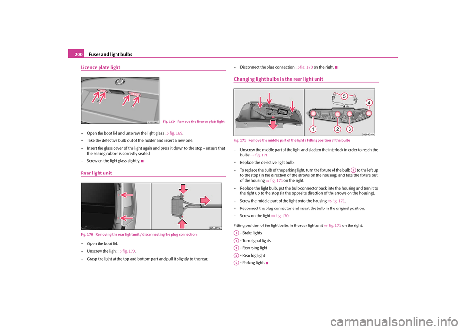
Licence plate light– Open the boot lid and unscrew the light glass fig. 169 .
– Take the defective bulb out of the holder and insert a new one.
– Insert the glass cover of the light again and press it down to the stop - ensure that
the sealing rubber is correctly seated.
– Screw on the light glass slightly.Rear light unitFig. 170 Removing the rear light uni t / disconnecting the plug connection– Open the boot lid.
– Unscrew the light fig. 170 .
– Grasp the light at the top and bottom pa rt and pull it slightly to the rear. – Disconnect the plug connection
fig. 170 on the right.
Changing light bulbs in the rear light unitFig. 171 Remove the middle part of the light / Fitting position of the bulbs– Unscrew the middle part of the light and slacken the interlock in order to reach the
bulbs fig. 171 .
– Replace the defective light bulb.
– To replace the bulb of the parking light, turn the fixture of the bulb to the left up to the stop (in the direction of the arrows on the housing) and take the fixture out
of the housing fig. 171 on the right.
– Replace the light bulb, put th e bulb connector back into the housing and turn it to
the right up to the stop (in the opposite direction of the arrows on the housing).
– Screw the middle part of the light onto the housing fig. 171 .
– Reconnect the plug connector and insert the bulb in the original position.
– Screw on the light fig. 170 .
Fitting position of the light bulbs in the rear light unit fig. 171 on the right.
- Brake lights
- Turn signal lights
- Reversing light
- Rear fog light
- Parking lights
Fig. 169 Remove the licence plate light
A5
A1A2A3A4A5
s16g.4.book Page 200 Wednesda y, February 10, 2010 3:53 PM