2010 NISSAN TIIDA Service
[x] Cancel search: ServicePage 58 of 3745
ON BOARD DIAGNOSTIC (OBD) SYSTEMAT-41
< SERVICE INFORMATION >
DE
F
G H
I
J
K L
M A
B
AT
N
O P
The OD OFF indicator lamp is located on the combination meter.
1. If the ignition switch stays ON after repair work, be su re to turn ignition switch OFF once. Wait at least 10
seconds and then turn it ON (engine stopped) again.
2. Perform “TCM SELF-DIAGNOSTIC PR OCEDURE (No Tools)”. Refer to AT-82, "
Diagnosis Procedure
without CONSULT-III". (The engine warm-up step can be skipped when performing the diagnosis only to
erase the DTC.)
3. Perform “OBD-II SELF-DIAGNOSTIC PROCEDURE (No tools)”. Refer to EC-84, "
Diagnosis Description"
(HR16DE), EC-542, "Emission-related Diagnostic Information" (MR18DE).
Malfunction Indicator Lamp (MIL)INFOID:0000000005397234
DESCRIPTION
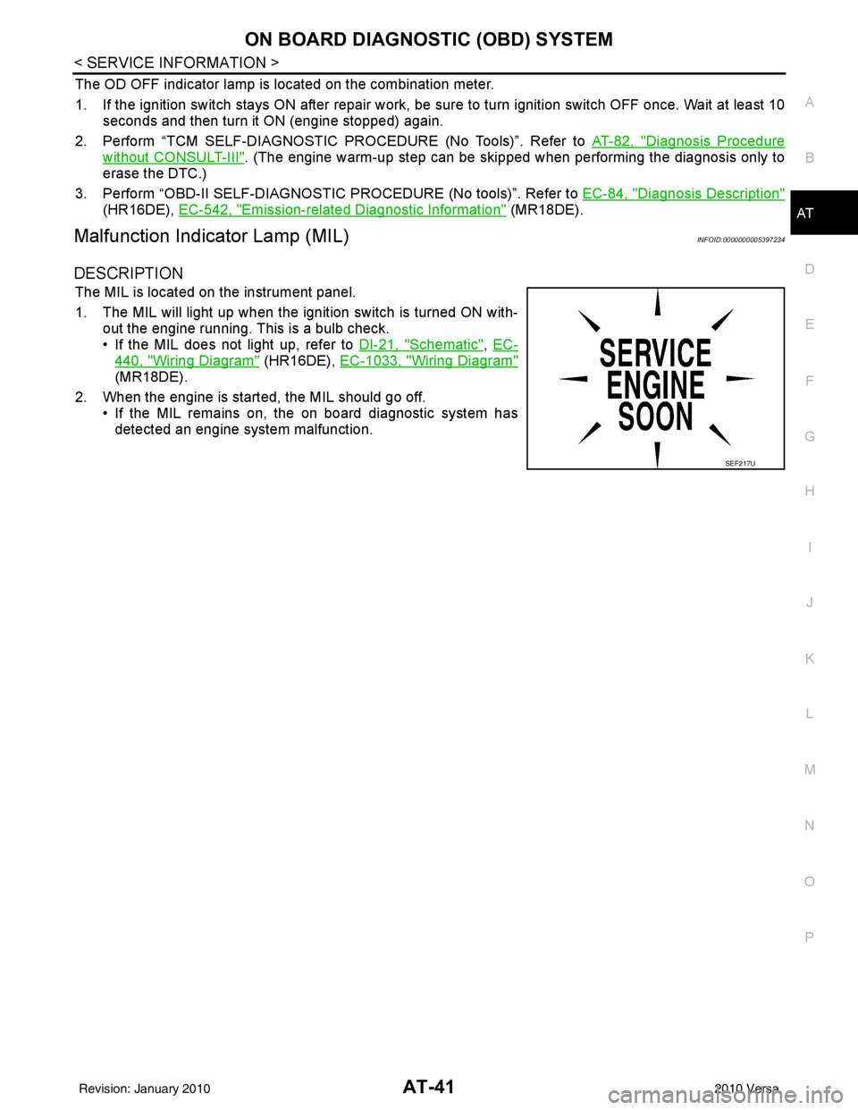
The MIL is located on the instrument panel.
1. The MIL will light up when the ignition switch is turned ON with-
out the engine running. This is a bulb check.
• If the MIL does not light up, refer to DI-21, "
Schematic", EC-
440, "Wiring Diagram" (HR16DE), EC-1033, "Wiring Diagram"
(MR18DE).
2. When the engine is start ed, the MIL should go off.
• If the MIL remains on, the on board diagnostic system has detected an engine system malfunction.
SEF217U
Revision: January 20102010 Versa
Page 59 of 3745

AT-42
< SERVICE INFORMATION >
TROUBLE DIAGNOSIS
TROUBLE DIAGNOSIS
DTC Inspection Priority ChartINFOID:0000000005397235
If some DTCs are displayed at the same time, perform inspections one by one based on the following priority
chart.
NOTE:
If DTC “CAN COMM CIRCUIT” is displayed with other DTCs, first perform the trouble diagnosis for
DTC “CAN COMM CIRCUIT”. Refer to AT- 8 7
.
Fail-SafeINFOID:0000000005397236
The TCM has an electronic Fail-safe mode. This allows t he vehicle to be driven even if a major electrical input/
output device circuit is damaged.
Under Fail-Safe, the vehicle always runs in 3GR, even wit h a shift lever position of “1”, “2” or “D”. The cus-
tomer may complain of sluggish or poor acceleration.
Always follow the “ AT-43, "
How to Perform Trouble Diagnosis for Quick and Accurate Repair" ”.
The SELF-DIAGNOSIS results will be as follows:
• The first SELF-DIAGNOSIS will indicate damage to the vehicle speed signal or the output speed sensor.
• During the next SELF-DIAGNOSIS, performed after checking the sensor, no damages will be indicated.
FAIL-SAFE FUNCTION
The following fail-safe functions allow vehicles to be driven even when sensor, switch or solenoid malfunction
occurs.
Output Speed Sensor
Vehicle speed signal is input from combination meter.
Accelerator Pedal Position Signal and Throttle Position Signal
TCM controls the throttle opening angle to a predetermined fixed position to enable driving if a malfunctioning
signal is input to TCM.
Transmission Range Switch
When the multiple transmission range switch signals are input to TCM, the priority of selector lever position
becomes “D”, “N”, “R”, “2” and “1” in order by internal TCM determination.
The use of 4GR is inhibited until normal operation resumes. Because the hydraulic circuit of the control valve
is switched by manual valve according to the selector lever position, however, actual operating condition of
vehicle becomes as follows.
Shift Solenoid Valve A and B
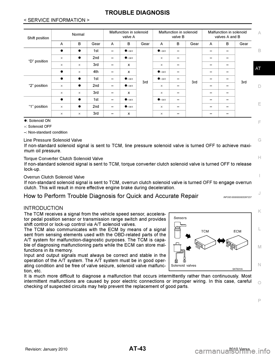
If non-standard solenoid signal is sent to TCM, use of certain gears is limited. Refer to chart shown below.
Priority Detected items
1 CAN communication line
2 Except above
Actual lever positionTransmission range switch input signal Running status
“P” “P” position and other position signals P
“R” “R” position and other position signals R
“N” “N” position and other position signals N
“D” “D” position and other position signals D
1 ⇔ D2 ⇔ D3 ⇔ D4
“2” “2” position and other position signals (Except “1” position)
21 ⇔ 22 ⇔ 23
“2” position and “1” position signals 21 ⇔ 22
“1” “1” position and other position signals (Except “2” position)
11 ⇔ 12 ⇔ 13
“1” position and “2” position signals 11 ⇔ 12
Revision: January 20102010 Versa
Page 60 of 3745
TROUBLE DIAGNOSISAT-43
< SERVICE INFORMATION >
DE
F
G H
I
J
K L
M A
B
AT
N
O P
�z : Solenoid ON
× : Solenoid OFF
–: Non-standard condition
Line Pressure Solenoid Valve
If non-standard solenoid signal is sent to TCM, line pre ssure solenoid valve is turned OFF to achieve maxi-
mum oil pressure.
Torque Converter Clutch Solenoid Valve
If non-standard solenoid signal is sent to TCM, torque conv erter clutch solenoid valve is turned OFF to release
lock-up.
Overrun Clutch Solenoid Valve
If non-standard solenoid signal is sent to TCM, overr un clutch solenoid valve is turned OFF to engage overrun
clutch. This will result in more effective engine brake during deceleration.
How to Perform Trouble Diagnosis for Quick and Accurate RepairINFOID:0000000005397237
INTRODUCTION
The TCM receives a signal from the vehicle speed sensor, accelera-
tor pedal position sensor or transmission range switch and provides
shift control or lock-up control via A/T solenoid valves.
The TCM also communicates with the ECM by means of a signal
sent from sensing elements used wit h the OBD-related parts of the
A/T system for malfunction-diagnostic purposes. The TCM is capa-
ble of diagnosing malfunctioning parts while the ECM can store mal-
functions in its memory.
Input and output signals must always be correct and stable in the
operation of the A/T system. T he A/T system must be in good oper-
ating condition and be free of valve seizure, solenoid valve malfunc-
tion, etc.
It is much more difficult to diagnose a malfunction that occurs intermittently rather than continuously. Most
intermittent malfunctions are caused by poor electric c onnections or improper wiring. In this case, careful
checking of suspected circuits may hel p prevent the replacement of good parts.
Shift positionNormal
Malfunction in solenoid
valve A Malfunction in solenoid
valve B Malfunction in solenoid
valves A and B
A BGearABGearABGearABGear
“D” position �z�z
1st –�z→×
3rd �z
→× –
3rd ––
3rd
×
�z2nd – �z→× ×–––
×× 3rd – x ×–––
�z ×4th – x �z→× –––
“2” position �z�z
1st –�z→× �z→× –––
× �z2nd – �z→× ×–––
×× 3rd – x ×–––
“1” position �z�z
1st –�z→× �z→× –––
× �z2nd – �z→× ×–––
×× 3rd – x ×–––
SAT631IA
Revision: January 20102010 Versa
Page 61 of 3745
AT-44
< SERVICE INFORMATION >
TROUBLE DIAGNOSIS
A visual check only, may not find the cause of the malfunctions. A
road test with CONSULT-III or a circuit tester connected should be
performed. Follow the "WORK FLOW" .
Before undertaking actual checks, take a few minutes to talk with a
customer who approaches with a driveability complaint. The cus-
tomer can supply good information about such malfunctions, espe-
cially intermittent ones. Find out what symptoms are present and
under what conditions they occu r. A “DIAGNOSTIC WORKSHEET”
like the example ("DIAGNOSTIC WORKSHEET" ) should be used.
Start your diagnosis by looking for “conventional” malfunctions first.
This will help troubleshoot driveability malfunctions on an electroni-
cally controlled engine vehicle.
Also check related Service bulletins for information.
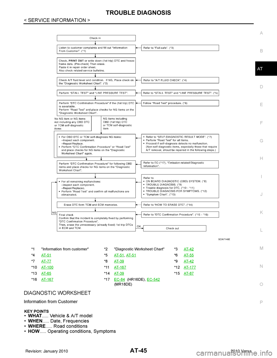
WORK FLOW
A good understanding of the malfunction conditions can make troubleshooting faster and more accurate. In
general, each customer feels differently about a malfuncti on. It is important to fully understand the symptoms
or conditions for a customer complaint.
Make good use of the two sheets provided, "Information from customer" and "Diagnostic Worksheet Chart" ,
to perform the best troubleshooting possible.
Work Flow Chart
SAT632I
SEF234G
Revision: January 20102010 Versa
Page 62 of 3745
TROUBLE DIAGNOSISAT-45
< SERVICE INFORMATION >
DE
F
G H
I
J
K L
M A
B
AT
N
O P
DIAGNOSTIC WORKSHEET
Information from Customer
KEY POINTS• WHAT ..... Vehicle & A/T model
• WHEN ..... Date, Frequencies
• WHERE ..... Road conditions
• HOW ..... Operating conditions, Symptoms
*1 "Information from customer" *2 "Diagnostic Worksheet Chart" *3 AT- 4 2
*4AT- 5 1*5AT- 5 1, AT- 5 1*6AT- 5 5
*7 AT- 7 7*8AT- 3 9*9AT- 4 2
*10 AT- 1 0 0*11AT- 1 6 7*12AT- 1 7 7
*13 AT- 6 5*14AT- 3 9*15AT- 8 7
*16 AT- 1 6 7*17EC-84 (HR16DE), EC-542
(MR18DE)
SCIA7146E
Revision: January 20102010 Versa
Page 63 of 3745

AT-46
< SERVICE INFORMATION >
TROUBLE DIAGNOSIS
Diagnostic Worksheet Chart
Customer name MR./MS Model & YearVIN
Trans. model EngineMileage
Incident Date Manuf. DateIn Service Date
Frequency �† Continuous �† Intermittent ( times a day)
Symptoms �† Vehicle does not move. ( �† Any position �† Particular position)
�† No up-shift ( �† 1st → 2nd �† 2nd → 3rd �† 3rd → 4th)
�† No down-shift ( �† 4th → 3rd �† 3rd → 2nd�† 2nd → 1st)
�† Lock-up malfunction
�† Shift point too high or too low.
�† Shift shock or slip ( �† N → D �† Lock-up �† Any drive position)
�† Noise or vibration
�† No kick down
�† No pattern select
�† Others
()
Malfunction indicator lamp (MIL) �† Continuously lit �† Not lit
1. �† Read the Fail-safe and listen to customer complaints. AT- 4 2,
"Information
from
customer"
2. �† Check A/T fluid AT- 1 7
�† Leakage (Follow specified procedure)
�† Fluid condition
�† Fluid level
3. �† Perform “STALL TEST” and “LINE PRESSURE TEST”. AT- 5 1
�†“STALL TEST”— Mark possible damaged components/others.
�† Torque converter one-way clutch
�† Reverse clutch
�† Forward clutch
�† Overrun clutch
�† Forward one-way clutch �†
Low & reverse brake
�† Low one-way clutch
�† Engine
�† Line pressure is low
�† Clutches and brakes except high clutch and
brake band are OK
�† “LINE PRESSURE TEST”— Suspected parts:
Revision: January 20102010 Versa
Page 64 of 3745
TROUBLE DIAGNOSISAT-47
< SERVICE INFORMATION >
DE
F
G H
I
J
K L
M A
B
AT
N
O P
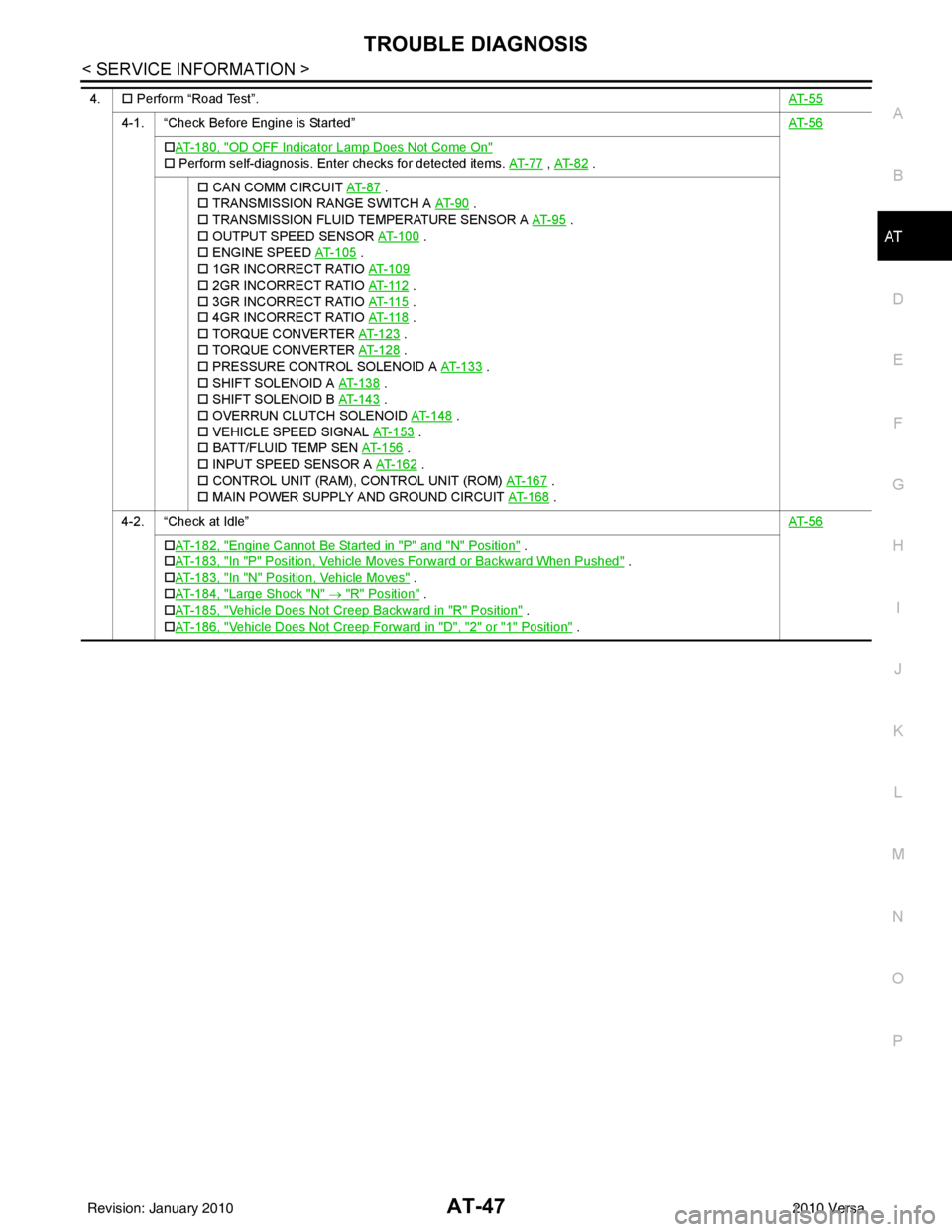
4. �† Perform “Road Test”. AT- 5 5
4-1. “Check Before Engine is Started” AT- 5 6
�†AT- 1 8 0 , "OD OFF Indicator Lamp Does Not Come On"
�† Perform self-diagnosis. Enter checks for detected items. AT- 7 7 , AT- 8 2 .
�† CAN COMM CIRCUIT AT- 8 7
.
�† TRANSMISSION RANGE SWITCH A AT- 9 0
.
�† TRANSMISSION FLUID TEMPERATURE SENSOR A AT- 9 5
.
�† OUTPUT SPEED SENSOR AT- 1 0 0
.
�† ENGINE SPEED AT- 1 0 5
.
�† 1GR INCORRECT RATIO AT- 1 0 9
�† 2GR INCORRECT RATIO AT- 11 2 .
�† 3GR INCORRECT RATIO AT- 11 5
.
�† 4GR INCORRECT RATIO AT- 11 8
.
�† TORQUE CONVERTER AT- 1 2 3
.
�† TORQUE CONVERTER AT- 1 2 8
.
�† PRESSURE CONTROL SOLENOID A AT- 1 3 3
.
�† SHIFT SOLENOID A AT- 1 3 8
.
�† SHIFT SOLENOID B AT- 1 4 3
.
�† OVERRUN CLUTCH SOLENOID AT- 1 4 8
.
�† VEHICLE SPEED SIGNAL AT- 1 5 3
.
�† BATT/FLUID TEMP SEN AT- 1 5 6
.
�† INPUT SPEED SENSOR A AT- 1 6 2
.
�† CONTROL UNIT (RAM), CONTROL UNIT (ROM) AT- 1 6 7
.
�† MAIN POWER SUPPLY AND GROUND CIRCUIT AT- 1 6 8
.
4-2. “Check at Idle” AT- 5 6
�†AT- 1 8 2 , "Engine Cannot Be Started in "P" and "N" Position" .
�† AT- 1 8 3 , "
In "P" Position, Vehicle Moves Forward or Backward When Pushed" .
�† AT- 1 8 3 , "
In "N" Position, Vehicle Moves" .
�† AT- 1 8 4 , "
Large Shock "N" → "R" Position" .
�† AT- 1 8 5 , "
Vehicle Does Not Creep Backward in "R" Position" .
�† AT- 1 8 6 , "
Vehicle Does Not Creep Forward in "D", "2" or "1" Position" .
Revision: January 20102010 Versa
Page 65 of 3745
AT-48
< SERVICE INFORMATION >
TROUBLE DIAGNOSIS
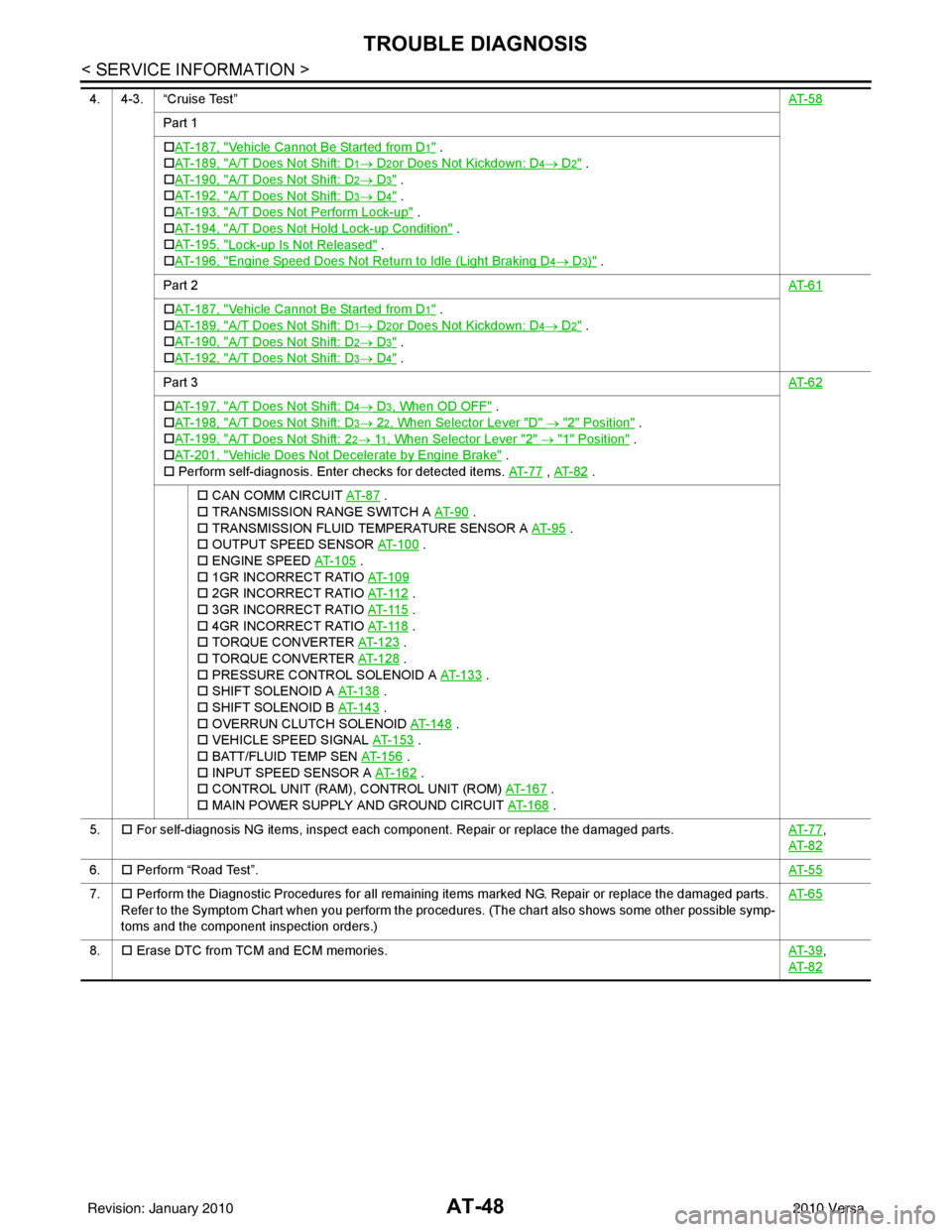
4. 4-3. “Cruise Test”AT- 5 8
Part 1
�†AT- 1 8 7 , "
Vehicle Cannot Be Started from D1" .
�† AT- 1 8 9 , "
A/T Does Not Shift: D1→ D2or Does Not Kickdown: D4→ D2" .
�† AT- 1 9 0 , "
A/T Does Not Shift: D2→ D3" .
�† AT- 1 9 2 , "
A/T Does Not Shift: D3→ D4" .
�† AT- 1 9 3 , "
A/T Does Not Perform Lock-up" .
�† AT- 1 9 4 , "
A/T Does Not Hold Lock-up Condition" .
�† AT- 1 9 5 , "
Lock-up Is Not Released" .
�† AT- 1 9 6 , "
Engine Speed Does Not Return to Idle (Light Braking D4→ D3)" .
Part 2 AT- 6 1
�†AT- 1 8 7 , "Vehicle Cannot Be Started from D1" .
�† AT- 1 8 9 , "
A/T Does Not Shift: D1→ D2or Does Not Kickdown: D4→ D2" .
�† AT- 1 9 0 , "
A/T Does Not Shift: D2→ D3" .
�† AT- 1 9 2 , "
A/T Does Not Shift: D3→ D4" .
Part 3 AT- 6 2
�†AT- 1 9 7 , "A/T Does Not Shift: D4→ D3, When OD OFF" .
�† AT- 1 9 8 , "
A/T Does Not Shift: D3→ 22, When Selector Lever "D" → "2" Position" .
�† AT- 1 9 9 , "
A/T Does Not Shift: 22→ 11, When Selector Lever "2" → "1" Position" .
�† AT- 2 0 1 , "
Vehicle Does Not Decelerate by Engine Brake" .
�† Perform self-diagnosis. Enter checks for detected items. AT- 7 7
, AT- 8 2 .
�† CAN COMM CIRCUIT AT- 8 7
.
�† TRANSMISSION RANGE SWITCH A AT- 9 0
.
�† TRANSMISSION FLUID TEMPERATURE SENSOR A AT- 9 5
.
�† OUTPUT SPEED SENSOR AT- 1 0 0
.
�† ENGINE SPEED AT- 1 0 5
.
�† 1GR INCORRECT RATIO AT- 1 0 9
�† 2GR INCORRECT RATIO AT- 11 2 .
�† 3GR INCORRECT RATIO AT- 11 5
.
�† 4GR INCORRECT RATIO AT- 11 8
.
�† TORQUE CONVERTER AT-123
.
�† TORQUE CONVERTER AT-128
.
�† PRESSURE CONTROL SOLENOID A AT- 1 3 3
.
�† SHIFT SOLENOID A AT- 1 3 8
.
�† SHIFT SOLENOID B AT- 1 4 3
.
�† OVERRUN CLUTCH SOLENOID AT- 1 4 8
.
�† VEHICLE SPEED SIGNAL AT- 1 5 3
.
�† BATT/FLUID TEMP SEN AT-156
.
�† INPUT SPEED SENSOR A AT- 1 6 2
.
�† CONTROL UNIT (RAM), CONTROL UNIT (ROM) AT-167
.
�† MAIN POWER SUPPLY AND GROUND CIRCUIT AT- 1 6 8
.
5. �† For self-diagnosis NG items, inspect each component. Repair or replace the damaged parts. AT- 7 7
,
AT- 8 2
6. �† Perform “Road Test”. AT- 5 5
7.�† Perform the Diagnostic Procedures for all remaining items marked NG. Repair or replace the damaged parts.
Refer to the Symptom Chart when you perform the procedures. (The chart also shows some other possible symp-
toms and the component inspection orders.) AT- 6 5
8.
�† Erase DTC from TCM and ECM memories. AT- 3 9,
AT- 8 2
Revision: January 20102010 Versa