2010 NISSAN TIIDA dimensions
[x] Cancel search: dimensionsPage 2581 of 3745
![NISSAN TIIDA 2010 Service Repair Manual EM-222
< SERVICE INFORMATION >[MR18DE]
CYLINDER BLOCK
• If measured value is out of the standard, replace flywheel.
Movement Amount in Radial (Rotation) Direction
Check the movement amount of radial NISSAN TIIDA 2010 Service Repair Manual EM-222
< SERVICE INFORMATION >[MR18DE]
CYLINDER BLOCK
• If measured value is out of the standard, replace flywheel.
Movement Amount in Radial (Rotation) Direction
Check the movement amount of radial](/manual-img/5/57397/w960_57397-2580.png)
EM-222
< SERVICE INFORMATION >[MR18DE]
CYLINDER BLOCK
• If measured value is out of the standard, replace flywheel.
Movement Amount in Radial (Rotation) Direction
Check the movement amount of radial (rot
ation) direction with the following procedure:
1. Install clutch cover bolt (1) to clutch cover mating hole, and place a torque wrench (A) on the extended line of the flywheel
(2) center line.
• Tighten bolt at a force of 9.8 N·m (1.0 kg-m, 87 in-lb) to keep itfrom loosening.
2. Put a mating mark on circumferences of the two flywheel masses without applying any load (Measurement standard
points).
3. Apply a force of 9.8 N·m (1.0 kg-m, 87 in-lb) in each direction, and mark the movement amount on the mass on the transaxle
side.
4. Measure the dimensions of movement amounts (A) and (B) on circumference of the flywheel on the transaxle side.
• If measured value is out of the standard, replace flywheel. Limit: 33.2 mm (1.307 in) or less.
PBIC4007E
Revision: January 20102010 Versa
Page 2583 of 3745
![NISSAN TIIDA 2010 Service Repair Manual EM-224
< SERVICE INFORMATION >[MR18DE]
SERVICE DATA AND SPECIFICATIONS (SDS)
Unit: mm (in)
VA LV E
Va l v e Ti m i n g
Unit: degree
( ): Valve timing control “ON”
Valve Dimensions
Unit: mm (in)
I NISSAN TIIDA 2010 Service Repair Manual EM-224
< SERVICE INFORMATION >[MR18DE]
SERVICE DATA AND SPECIFICATIONS (SDS)
Unit: mm (in)
VA LV E
Va l v e Ti m i n g
Unit: degree
( ): Valve timing control “ON”
Valve Dimensions
Unit: mm (in)
I](/manual-img/5/57397/w960_57397-2582.png)
EM-224
< SERVICE INFORMATION >[MR18DE]
SERVICE DATA AND SPECIFICATIONS (SDS)
Unit: mm (in)
VA LV E
Va l v e Ti m i n g
Unit: degree
( ): Valve timing control “ON”
Valve Dimensions
Unit: mm (in)
Items
StandardLimit
Head surface distortion —0.1 (0.004)
Normal cylinder head height (H) 130.9 (5.15)—
Groove of No. 1 journal 4.000 - 4.300 (0.1575 - 0.1587) —
PBIC0924E
Valve timing
abcde f
212 224-8 (32) 52 (12) 725
PBIC4542E
Valve head diameter (D) Intake 33.8 - 34.1 (1.331 - 1.343)
Exhaust
27.6 - 27.9 (1.087 - 1.098)
Valve length (L) Intake
106.27 (4.184)
Exhaust 105.26 (4.144)
SEM188A
Revision: January 20102010 Versa
Page 2667 of 3745

GI-1
GENERAL INFORMATION
C
DE
F
G H
I
J
K L
M B
GI
SECTION GI
N
O P
CONTENTS
GENERAL INFORMATION
SERVICE INFORMATION .. ..........................2
PRECAUTIONS .............................................. .....2
Description .......................................................... ......2
Precaution for Supplemental Restraint System
(SRS) "AIR BAG" and "SEAT BELT PRE-TEN-
SIONER" ...................................................................
2
Precaution Necessary for Steering Wheel Rota-
tion After Battery Disconnect ............................... ......
2
General Precaution ...................................................3
Precaution for Three Way Catalyst ...........................4
Precaution for Fuel (Unleaded Regular Gasoline
Recommended) .........................................................
4
Precaution for Multiport Fuel Injection System or
Engine Control System .............................................
5
Precaution for Hoses .................................................5
Precaution for Engine Oils ........................................6
Precaution for Air Conditioning .................................6
HOW TO USE THIS MANUAL ............................7
Description .......................................................... ......7
Terms ........................................................................7
Units ..........................................................................7
Contents ....................................................................7
Relation between Illustrations and Descriptions .......8
Component ................................................................8
How to Follow Trouble Diagnosis ..............................9
How to Read Wiring Diagram ..................................13
Abbreviations ...................................................... ....20
SERVICE INFORMATION FOR ELECTRICAL
INCIDENT ...........................................................
22
How to Check Terminal ...........................................22
How to Perform Efficient Diagnosis for an Electri-
cal Incident .......................................................... ....
25
Control Units and Electrical Parts ............................32
CONSULT-III CHECKING SYSTEM .................35
Description ...............................................................35
Function and System Application ............................35
CONSULT-III Data Link Connector (DLC) Circuit ....36
LIFTING POINT .................................................38
Special Service Tool ................................................38
Garage Jack and Safety Stand and 2-Pole Lift .......38
Board-On Lift ...........................................................39
TOW TRUCK TOWING .....................................40
Tow Truck Towing ...................................................40
Vehicle Recovery (Freeing a Stuck Vehicle) ...........40
TIGHTENING TORQUE OF STANDARD
BOLTS ...............................................................
41
Tightening Torque Table .........................................41
RECOMMENDED CHEMICAL PRODUCTS
AND SEALANTS ...............................................
42
Recommended Chemical Product and Sealant .......42
IDENTIFICATION INFORMATION ....................43
Model Variation ........................................................43
Dimensions ..............................................................46
Wheels & Tires ........................................................46
TERMINOLOGY ................................................48
SAE J1930 Terminology List ...................................48
Revision: January 20102010 Versa
Page 2712 of 3745

GI-46
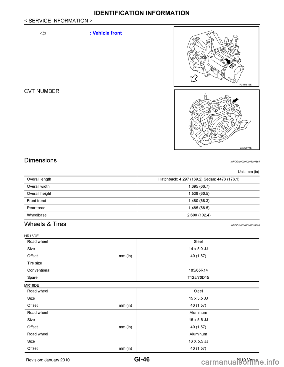
< SERVICE INFORMATION >
IDENTIFICATION INFORMATION
CVT NUMBER
DimensionsINFOID:0000000005399865
Unit: mm (in)
Wheels & TiresINFOID:0000000005399866
HR16DE
MR18DE
: Vehicle front
PCIB1612E
LAIA0074E
Overall lengthHatchback: 4,297 (169.2) Sedan: 4473 (176.1)
Overall width 1,695 (66.7)
Overall height 1,538 (60.5)
Front tread 1,480 (58.3)
Rear tread 1,485 (58.5)
Wheelbase 2,600 (102.4)
Road wheel St ee l
Size 14 x 5.0 JJ
Offset mm (in)40 (1.57)
Tire size
Conventional 185/65R14
Spare T125/70D15
Road wheel St ee l
Size 15 x 5.5 JJ
Offset mm (in)40 (1.57)
Road wheel Aluminum
Size 15 x 5.5 JJ
Offset mm (in)40 (1.57)
Road wheel Aluminum
Size 16 X 5.5 JJ
Offset mm (in)40 (1.57)
Revision: January 20102010 Versa
Page 3020 of 3745

HEADLAMP (FOR USA)LT-25
< SERVICE INFORMATION >
C
DE
F
G H
I
J
L
M A
B
LT
N
O P
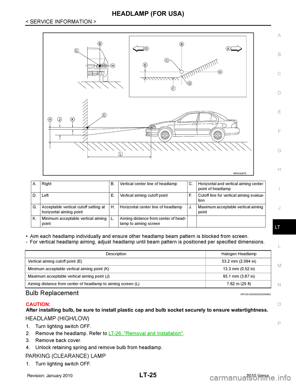
• Aim each headlamp individually and ensure other headlamp beam pattern is blocked from screen.
- For vertical headlamp aiming, adjust headlamp until beam pattern is positioned per specified dimensions.
Bulb ReplacementINFOID:0000000005394893
CAUTION:
After installing bulb, be sure to install plastic cap and bulb socket securely to ensure watertightness.
HEADLAMP (HIGH/LOW)
1. Turn lighting switch OFF.
2. Remove the headlamp. Refer to LT-26, "
Removal and Installation".
3. Remove back cover.
4. Unlock retaining spring and remove bulb from headlamp.
PARKING (CLEARANCE) LAMP
1. Turn lighting switch OFF.
A. Right B. Vertical center line of headlamp C. Horizontal and vertical aiming center
point of headlamp
D. Left E. Vertical aiming cutoff pointF. Cutoff line for vertical aiming evalua-
tion
G. Acceptable vertical cutoff setting at horizontal aiming point H. Horizontal center line of headlamp J. Maximum acceptable vertical aiming
point
K. Minimum acceptable vertical aiming point L. Aiming distance from center of head-
lamp to aiming screen
WKIA4287E
Description Halogen Headlamp
Vertical aiming cutoff point (E) 53.2 mm (2.094 in)
Minimum acceptable vertical aiming point (K) 13.3 mm (0.52 in)
Maximum acceptable vertical aiming point (J) 93.1 mm (3.67 in)
Aiming distance from center of headlamp to aiming screen (L) 7.62 m (25 ft)
Revision: January 20102010 Versa
Page 3034 of 3745

HEADLAMP (FOR CANADA) - DAYTIME LIGHT SYSTEM -
LT-39
< SERVICE INFORMATION >
C
D E
F
G H
I
J
L
M A
B
LT
N
O P
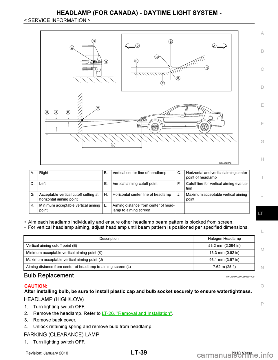
• Aim each headlamp individually and ensure other headlamp beam pattern is blocked from screen.
- For vertical headlamp aiming, adjust headlamp until beam pattern is positioned per specified dimensions.
Bulb ReplacementINFOID:0000000005394909
CAUTION:
After installing bulb, be sure to install plastic cap and bulb socket securely to ensure watertightness.
HEADLAMP (HIGH/LOW)
1. Turn lighting switch OFF.
2. Remove the headlamp. Refer to LT-26, "
Removal and Installation".
3. Remove back cover.
4. Unlock retaining spring and remove bulb from headlamp.
PARKING (CLEARANCE) LAMP
1. Turn lighting switch OFF.
A. Right B. Vertical center line of headlamp C. Horizontal and vertical aiming center
point of headlamp
D. Left E. Vertical aiming cutoff pointF. Cutoff line for vertical aiming evalua-
tion
G. Acceptable vertical cutoff setting at horizontal aiming point H. Horizontal center line of headlamp J. Maximum acceptable vertical aiming
point
K. Minimum acceptable vertical aiming point L. Aiming distance from center of head-
lamp to aiming screen
WKIA4287E
Description Halogen Headlamp
Vertical aiming cutoff point (E) 53.2 mm (2.094 in)
Minimum acceptable vertical aiming point (K) 13.3 mm (0.52 in)
Maximum acceptable vertical aiming point (J) 93.1 mm (3.67 in)
Aiming distance from center of headlamp to aiming screen (L) 7.62 m (25 ft)
Revision: January 20102010 Versa
Page 3115 of 3745
![NISSAN TIIDA 2010 Service Repair Manual PRECAUTIONSLU-3
< PRECAUTION > [HR16DE]
C
D
E
F
G H
I
J
K L
M A
LU
NP
O
5. When the repair work is completed, return the ignition switch to the
″LOCK ″ position before connecting
the battery cabl NISSAN TIIDA 2010 Service Repair Manual PRECAUTIONSLU-3
< PRECAUTION > [HR16DE]
C
D
E
F
G H
I
J
K L
M A
LU
NP
O
5. When the repair work is completed, return the ignition switch to the
″LOCK ″ position before connecting
the battery cabl](/manual-img/5/57397/w960_57397-3114.png)
PRECAUTIONSLU-3
< PRECAUTION > [HR16DE]
C
D
E
F
G H
I
J
K L
M A
LU
NP
O
5. When the repair work is completed, return the ignition switch to the
″LOCK ″ position before connecting
the battery cables. (At this time, the steering lock mechanism will engage.)
6. Perform a self-diagnosis check of al l control units using CONSULT-III.
Precaution for Liquid GasketINFOID:0000000005398152
REMOVAL OF LIQUID GASKET SEALING
• After removing nuts and bolts, separate the mating surface, using Tool and remove old liquid gasket sealing.
CAUTION:
Be careful not to damage the mating surfaces.
• Tap Tool to insert it (1), and then slide it by tapping on the side (2) as shown.
• In areas where Tool is difficult to use, use plastic hammer to lightly tap the parts, to remove it.
CAUTION:
If for some unavoidable reason suitable tool such as screw-
driver is used, be careful not to damage the mating surfaces.
LIQUID GASKET APPLICATION PROCEDURE
1. Remove old liquid gasket adhering to the liquid gasket applica- tion surface and the mating surface, using scraper.
• Remove liquid gasket completely from the groove of the liquidgasket application surface, bolts, and bolt holes.
2. Thoroughly clean the mating surfaces and remove adhering moisture, grease and foreign materials.
3. Attach liquid gasket tube to Tool.
Use Genuine RTV Silicone Seal ant or equivalent. Refer to GI-42, "
Recommended Chemical Prod-
uct and Sealant".
4. Apply liquid gasket without breaks to the specified location with the specified dimensions. • If there is a groove for the liquid gasket application, apply liquid gasket to the groove.
• As for the bolt holes, normally apply liquid gasket inside theholes. Occasionally, it should be applied outside the holes.
Make sure to read the text of service manual.
• Within five minutes of liquid gasket application, install the mat-
ing component.
• If liquid gasket protrudes, wipe it off immediately.
• Do not retighten nuts or bolts after the installation.
• After 30 minutes or more have passed from the installation, fill engine oil and engine coolant.
CAUTION:
If there are specific instructions in this manual, observe them.
Tool number : KV10111100 (J-37228)
WBIA0566E
Tool number : WS39930000 ( — )
PBIC0003E
WBIA0567E
SEM159F
Revision: January 20102010 Versa
Page 3125 of 3745
![NISSAN TIIDA 2010 Service Repair Manual PRECAUTIONSLU-13
< SERVICE INFORMATION > [MR18DE]
C
D
E
F
G H
I
J
K L
M A
LU
NP
O
5. When the repair work is completed, return the ignition switch to the
″LOCK ″ position before connecting
the ba NISSAN TIIDA 2010 Service Repair Manual PRECAUTIONSLU-13
< SERVICE INFORMATION > [MR18DE]
C
D
E
F
G H
I
J
K L
M A
LU
NP
O
5. When the repair work is completed, return the ignition switch to the
″LOCK ″ position before connecting
the ba](/manual-img/5/57397/w960_57397-3124.png)
PRECAUTIONSLU-13
< SERVICE INFORMATION > [MR18DE]
C
D
E
F
G H
I
J
K L
M A
LU
NP
O
5. When the repair work is completed, return the ignition switch to the
″LOCK ″ position before connecting
the battery cables. (At this time, the steering lock mechanism will engage.)
6. Perform a self-diagnosis check of al l control units using CONSULT-III.
Precaution for Liquid GasketINFOID:0000000005398165
REMOVAL OF LIQUID GASKET SEALING
• After removing nuts and bolts, separate the mating surface, using Tool and remove old liquid gasket sealing.
CAUTION:
Be careful not to damage the mating surfaces.
• Tap Tool to insert it (1), and then slide it by tapping on the side (2) as shown.
• In areas where Tool is difficult to use, use plastic hammer to lightly tap the parts, to remove it.
CAUTION:
If for some unavoidable reason suitable tool such as screw-
driver is used, be careful not to damage the mating surfaces.
LIQUID GASKET APPLICATION PROCEDURE
1. Remove old liquid gasket adhering to the liquid gasket applica- tion surface and the mating surface, using scraper.
• Remove liquid gasket completely from the groove of the liquidgasket application surface, bolts, and bolt holes.
2. Thoroughly clean the mating surfaces and remove adhering moisture, grease and foreign materials.
3. Attach liquid gasket tube to Tool.
Use Genuine RTV Silicone Seal ant or equivalent. Refer to GI-42, "
Recommended Chemical Prod-
uct and Sealant".
4. Apply liquid gasket without breaks to the specified location with the specified dimensions. • If there is a groove for the liquid gasket application, apply liquid gasket to the groove.
• As for the bolt holes, normally apply liquid gasket inside theholes. Occasionally, it should be applied outside the holes.
Make sure to read the text of service manual.
• Within five minutes of liquid gasket application, install the mat-
ing component.
• If liquid gasket protrudes, wipe it off immediately.
• Do not retighten nuts or bolts after the installation.
• After 30 minutes or more have passed from the installation, fill engine oil and engine coolant.
CAUTION:
If there are specific instructions in this manual, observe them.
Tool number : KV10111100 (J-37228)
WBIA0566E
Tool number : WS39930000 ( — )
PBIC0003E
WBIA0567E
SEM159F
Revision: January 20102010 Versa