2010 NISSAN TIIDA cooling
[x] Cancel search: coolingPage 1023 of 3745
RADIATORCO-41
< SERVICE INFORMATION > [MR18DE]
C
D
E
F
G H
I
J
K L
M A
CO
NP
O
Removal and InstallationINFOID:0000000005398215
WARNING:
Do not remove radiator cap when the engine is
hot. Serious burns could occur from high-pressure
engine coolant escaping from radiator. Wrap a thick cl oth around the cap. Slowly turn it a quarter of a
turn to release built-up pressure. Carefully remove radiator cap by turning it all the way.
REMOVAL
1. Remove engine under cover. Refer to EI-15, "Removal and Installation".
2. Drain engine coolant from radiator. Refer to CO-36, "
Changing Engine Coolant".
CAUTION:
• Perform this step when engine is cold.
• Do not spill engine coolant on drive belt.
3. Remove air duct (inlet). Refer to EM-135
.
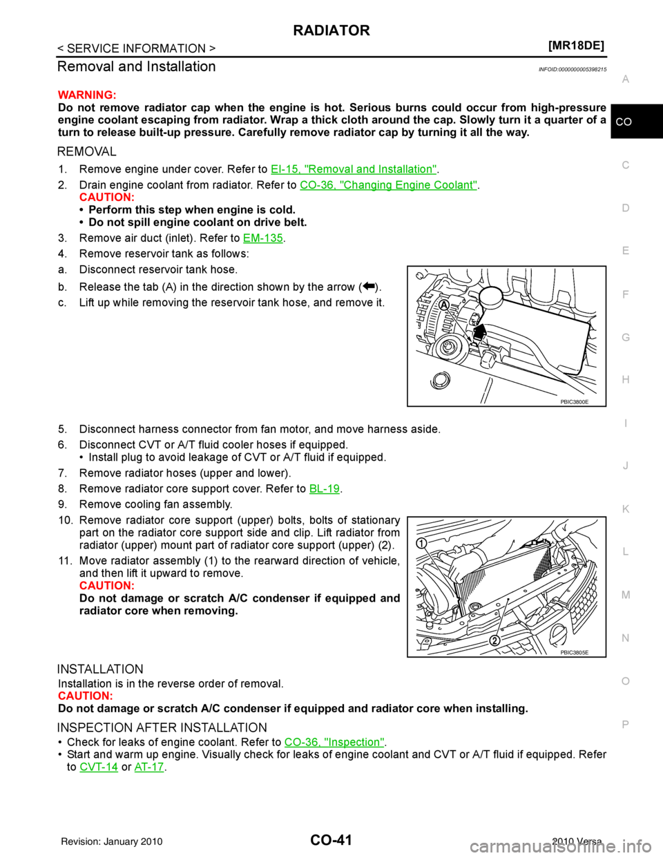
4. Remove reservoir tank as follows:
a. Disconnect reservoir tank hose.
b. Release the tab (A) in the direction shown by the arrow ( ).
c. Lift up while removing the reservoir tank hose, and remove it.
5. Disconnect harness connector from fan motor, and move harness aside.
6. Disconnect CVT or A/T fluid cooler hoses if equipped. • Install plug to avoid leakage of CVT or A/T fluid if equipped.
7. Remove radiator hoses (upper and lower).
8. Remove radiator core support cover. Refer to BL-19
.
9. Remove cooling fan assembly.
10. Remove radiator core support (upper) bolts, bolts of stationary part on the radiator core support side and clip. Lift radiator from
radiator (upper) mount part of radiator core support (upper) (2).
11. Move radiator assembly (1) to the rearward direction of vehicle, and then lift it upward to remove.
CAUTION:
Do not damage or scratch A/C condenser if equipped and
radiator core when removing.
INSTALLATION
Installation is in the reverse order of removal.
CAUTION:
Do not damage or scratch A/C condenser if eq uipped and radiator core when installing.
INSPECTION AFTER INSTALLATION
• Check for leaks of engine coolant. Refer to CO-36, "Inspection".
• Start and warm up engine. Visually check for leaks of engine coolant and CVT or A/T fluid if equipped. Refer
to CVT-14
or AT- 1 7.
PBIC3800E
PBIC3805E
Revision: January 20102010 Versa
Page 1024 of 3745
CO-42
< SERVICE INFORMATION >[MR18DE]
COOLING FAN
COOLING FAN
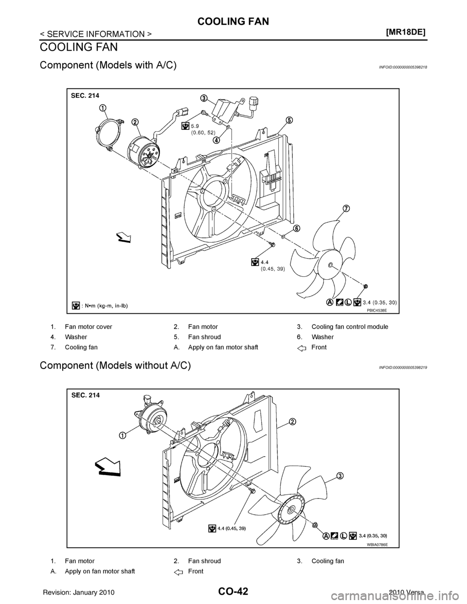
Component (Models with A/C)INFOID:0000000005398218
Component (Models without A/C)INFOID:0000000005398219
1. Fan motor cover
2. Fan motor3. Cooling fan control module
4. Washer 5. Fan shroud 6. Washer
7. Cooling fan A. Apply on fan motor shaft Front
PBIC4538E
1. Fan motor 2. Fan shroud3. Cooling fan
A. Apply on fan motor shaft Front
WBIA0786E
Revision: January 20102010 Versa
Page 1025 of 3745
COOLING FANCO-43
< SERVICE INFORMATION > [MR18DE]
C
D
E
F
G H
I
J
K L
M A
CO
NP
O
Removal and InstallationINFOID:0000000005398220
REMOVAL
1. Partially drain engine coolant from radiator. Refer to
CO-36, "Changing Engine Coolant".
CAUTION:
• Perform this step when engine is cold.
• Do not spill engine coolant on drive belt.
2. Remove air duct (inlet). Refer to EM-135, "
Component".
3. Remove reservoir tank. Refer to CO-40, "
Component".
4. Disconnect radiator hose (upper) at radiator side. Refer to CO-40, "
Component".
5. Disconnect harness connectors from fan motor, and move harness aside.
6. Remove cooling fan assembly. CAUTION:
Be careful not to damage or scratch the radiator core.
INSTALLATION
Installation is in the reverse order of removal.
• Cooling fans are controlled by ECM. For details, refer to EC-910, "
System Description".
CAUTION:
Be careful not to damage or scratch the radiator core.
Disassembly and AssemblyINFOID:0000000005398221
DISASSEMBLY
1. Remove cooling fan from fan motor.
2. Remove fan motor from fan shroud.
INSPECTION AFTER DISASSEMBLY
Inspect cooling fan for crack or unusual bend.
• If anything is found, replace cooling fan.
ASSEMBLY
Assembly is in the reverse order of disassembly.
Revision: January 20102010 Versa
Page 1267 of 3745
EC-2
CAN COMMUNICATION ...................................59
System Description .................................................59
COOLING FAN CONTROL ...............................60
System Diagram .................................................. ...60
System Description .................................................60
Component Parts Location ...................................62
Component Description ..........................................66
EVAPORATIVE EMISSION SYSTEM ...............68
System Diagram .................................................. ...68
System Description .................................................68
Component Parts Location ...................................72
Component Description .........................................76
INTAKE VALVE TIMING CONTROL .................78
System Diagram .................................................. ...78
System Description .................................................78
Component Parts Location ...................................79
Component Description ..........................................83
ON BOARD DIAGNOSTIC (OBD) SYSTEM .....84
Diagnosis Description .......................................... ...84
CONSULT-III Function ...........................................98
Diagnosis Tool Function ......................................104
COMPONENT DIAGNOSIS .......................106
TROUBLE DIAGNOSIS - SPECIFICATION
VALUE ............................................................ .
106
Description ........................................................... ..106
Component Function Check ..................................106
Diagnosis Procedure .............................................107
TROUBLE DIAGNOSIS FOR INTERMITTENT
INCIDENT ........................................................
114
Description ........................................................... ..114
Diagnosis Procedure .............................................114
POWER SUPPLY AND GROUND CIRCUIT ...115
Wiring Diagram .................................................... ..115
Diagnosis Procedure .............................................115
Ground Inspection .................................................119
U0101 CAN COMM CIRCUIT ..........................120
Description ........................................................... ..120
DTC Logic ..............................................................120
Wiring Diagram ......................................................121
Diagnosis Procedure .............................................121
U0140 CAN COMM CIRCUIT ..........................122
Description ........................................................... ..122
DTC Logic ..............................................................122
Wiring Diagram ......................................................123
Diagnosis Procedure .............................................123
U1001 CAN COMM CIRCUIT ..........................124
Description ........................................................... ..124
DTC Logic ..............................................................124
Wiring Diagram ......................................................125
Diagnosis Procedure .............................................125
P0011 IVT CONTROL ......................................126
DTC Logic ............................................................ .126
Diagnosis Procedure .............................................127
Component Inspection ..........................................128
P0031, P0032 A/F SENSOR 1 HEATER ..........130
Description ........................................................... .130
DTC Logic .............................................................130
Wiring Diagram .....................................................131
Diagnosis Procedure .............................................131
Component Inspection ..........................................133
P0037, P0038 HO2S2 HEATER .......................134
Description ........................................................... .134
DTC Logic .............................................................134
Wiring Diagram .....................................................135
Diagnosis Procedure .............................................135
Component Inspection ..........................................137
P0075 IVT CONTROL SOLENOID VALVE ......138
Description ........................................................... .138
DTC Logic .............................................................138
Wiring Diagram .....................................................139
Diagnosis Procedure .............................................139
Component Inspection ..........................................140
P0101 MAF SENSOR .......................................142
Description ........................................................... .142
DTC Logic .............................................................142
Component Function Check .................................143
Wiring Diagram .....................................................145
Diagnosis Procedure .............................................145
Component Inspection ..........................................147
P0102, P0103 MAF SENSOR ..........................150
Description ........................................................... .150
DTC Logic .............................................................150
Wiring Diagram .....................................................151
Diagnosis Procedure .............................................151
Component Inspection ..........................................153
P0112, P0113 IAT SENSOR ............................156
Description ............................................................156
DTC Logic .............................................................156
Wiring Diagram .....................................................157
Diagnosis Procedure .............................................157
Component Inspection ..........................................158
P0116 ECT SENSOR .......................................159
Description ............................................................159
DTC Logic .............................................................159
Diagnosis Procedure .............................................160
Component Inspection ..........................................160
P0117, P0118 ECT SENSOR ...........................161
Description ............................................................161
DTC Logic .............................................................161
Wiring Diagram .....................................................162
Diagnosis Procedure .............................................162
Component Inspection ..........................................163
Revision: January 20102010 Versa
Page 1271 of 3745
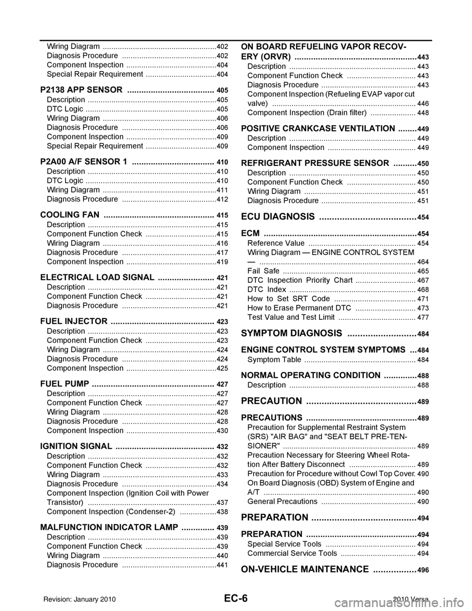
EC-6
Wiring Diagram ......................................................402
Diagnosis Procedure .............................................402
Component Inspection ...........................................404
Special Repair Requirement ..................................404
P2138 APP SENSOR ..................................... .405
Description ........................................................... ..405
DTC Logic ..............................................................405
Wiring Diagram ......................................................406
Diagnosis Procedure .............................................406
Component Inspection ...........................................409
Special Repair Requirement ..................................409
P2A00 A/F SENSOR 1 ................................... .410
Description ........................................................... ..410
DTC Logic ..............................................................410
Wiring Diagram ......................................................411
Diagnosis Procedure .............................................412
COOLING FAN ................................................415
Description ........................................................... ..415
Component Function Check ..................................415
Wiring Diagram ......................................................416
Diagnosis Procedure .............................................417
Component Inspection ...........................................419
ELECTRICAL LOAD SIGNAL .........................421
Description ........................................................... ..421
Component Function Check ..................................421
Diagnosis Procedure .............................................421
FUEL INJECTOR .............................................423
Description ........................................................... ..423
Component Function Check ..................................423
Wiring Diagram ......................................................424
Diagnosis Procedure .............................................424
Component Inspection ...........................................425
FUEL PUMP .....................................................427
Description ........................................................... ..427
Component Function Check ..................................427
Wiring Diagram ......................................................428
Diagnosis Procedure .............................................428
Component Inspection ...........................................430
IGNITION SIGNAL ...........................................432
Description ........................................................... ..432
Component Function Check ..................................432
Wiring Diagram ......................................................433
Diagnosis Procedure .............................................434
Component Inspection (Ignition Coil with Power
Transistor) .............................................................
437
Component Inspection (Condenser-2) ..................438
MALFUNCTION INDICATOR LAMP ...............439
Description ........................................................... ..439
Component Function Check ..................................439
Wiring Diagram ......................................................440
Diagnosis Procedure .............................................441
ON BOARD REFUELING VAPOR RECOV-
ERY (ORVR) .....................................................
443
Description ........................................................... .443
Component Function Check .................................443
Diagnosis Procedure .............................................443
Component Inspection (Refueling EVAP vapor cut
valve) ................................................................... .
446
Component Inspection (Drain filter) ......................448
POSITIVE CRANKCASE VENTILATION .........449
Description ........................................................... .449
Component Inspection ..........................................449
REFRIGERANT PRESSURE SENSOR ...........450
Description ........................................................... .450
Component Function Check .................................450
Wiring Diagram .....................................................451
Diagnosis Procedure .............................................451
ECU DIAGNOSIS ......................................454
ECM ................................................................ ..454
Reference Value .................................................. .454
Wiring Diagram — ENGINE CONTROL SYSTEM
— ..........................................................................
464
Fail Safe ...............................................................465
DTC Inspection Priority Chart .............................467
DTC Index ............................................................468
How to Set SRT Code .......................................471
How to Erase Permanent DTC .............................473
Test Value and Test Limit .....................................477
SYMPTOM DIAGNOSIS ...........................484
ENGINE CONTROL SYSTEM SYMPTOMS .. ..484
Symptom Table .................................................... .484
NORMAL OPERATING CONDITION ...............488
Description ........................................................... .488
PRECAUTION ...........................................489
PRECAUTIONS .............................................. ..489
Precaution for Supplemental Restraint System
(SRS) "AIR BAG" and "SEAT BELT PRE-TEN-
SIONER" .............................................................. .
489
Precaution Necessary for Steering Wheel Rota-
tion After Battery Disconnect ................................
489
Precaution for Procedure without Cowl Top Cover .490
On Board Diagnosis (OBD) System of Engine and
A/T ........................................................................
490
General Precautions .............................................490
PREPARATION .........................................494
PREPARATION .............................................. ..494
Special Service Tools .......................................... .494
Commercial Service Tools ....................................494
ON-VEHICLE MAINTENANCE .................496
Revision: January 20102010 Versa
Page 1295 of 3745
EC-30
< FUNCTION DIAGNOSIS >[HR16DE]
ENGINE CONTROL SYSTEM
System Description
INFOID:0000000005398249
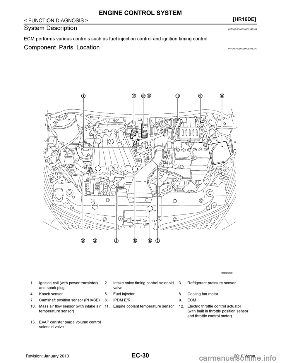
ECM performs various controls such as fuel injection control and ignition timing control.
Component Parts LocationINFOID:0000000005398250
1. Ignition coil (with power transistor) and spark plug 2. Intake valve timing control solenoid
valve 3. Refrigerant pressure sensor
4. Knock sensor 5. Fuel injector6. Cooling fan motor
7. Camshaft position sensor (PHASE) 8. IPDM E/R 9. ECM
10. Mass air flow sensor (with intake air temperature sensor) 11. Engine coolant temperature sensor 12. Electric throttle control actuator
(with built in throttle position sensor
and throttle control motor)
13. EVAP canister purge volume control solenoid valve
PBIB2939E
Revision: January 20102010 Versa
Page 1299 of 3745
EC-34
< FUNCTION DIAGNOSIS >[HR16DE]
ENGINE CONTROL SYSTEM
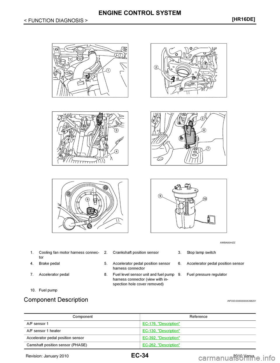
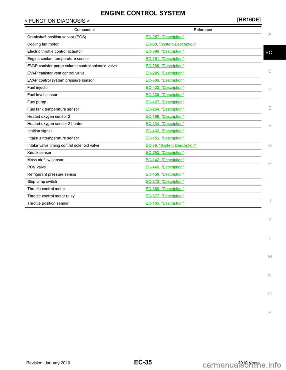
Component Description
INFOID:0000000005398251
1. Cooling fan motor harness connec- tor 2. Crankshaft position sensor
3. Stop lamp switch
4. Brake pedal 5. Accelerator pedal position sensor
harness connector 6. Accelerator pedal position sensor
7. Accelerator pedal 8. Fuel level sensor unit and fuel pump
harness connector (view with in-
spection hole cover removed) 9. Fuel pressure regulator
10. Fuel pump
AWBIA0044ZZ
Component Reference
A/F sensor 1 EC-176, "
Description"
A/F sensor 1 heaterEC-130, "Description"
Accelerator pedal position sensorEC-392, "Description"
Camshaft position sensor (PHASE)EC-262, "Description"
Revision: January 20102010 Versa
Page 1300 of 3745
ENGINE CONTROL SYSTEMEC-35
< FUNCTION DIAGNOSIS > [HR16DE]
C
D
E
F
G H
I
J
K L
M A
EC
NP
O
Crankshaft position sensor (POS)
EC-257, "Description"
Cooling fan motorEC-60, "System Description"
Electric throttle control actuatorEC-390, "Description"
Engine coolant temperature sensorEC-161, "Description"
EVAP canister purge volume control solenoid valveEC-285, "Description"
EVAP canister vent control valveEC-295, "Description"
EVAP control system pressure sensorEC-306, "Description"
Fuel injectorEC-423, "Description"
Fuel level sensorEC-336, "Description"
Fuel pumpEC-427, "Description"
Fuel tank temperature sensorEC-234, "Description"
Heated oxygen sensor 2EC-198, "Description"
Heated oxygen sensor 2 heaterEC-134, "Description"
Ignition signalEC-432, "Description"
Intake air temperature sensorEC-156, "Description"
Intake valve timing control solenoid valveEC-78, "System Description"
Knock sensorEC-253, "Description"
Mass air flow sensorEC-142, "Description"
PCV valveEC-449, "Description"
Refrigerant pressure sensorEC-450, "Description"
Stop lamp switchEC-373, "Description"
Throttle control motorEC-386, "Description"
Throttle control motor relayEC-377, "Description"
Throttle position sensorEC-165, "Description"
Component Reference
Revision: January 20102010 Versa