2010 NISSAN TIIDA Body front
[x] Cancel search: Body frontPage 705 of 3745
BL-196
< SERVICE INFORMATION >
TRUNK LID OPENER
TRUNK LID OPENER
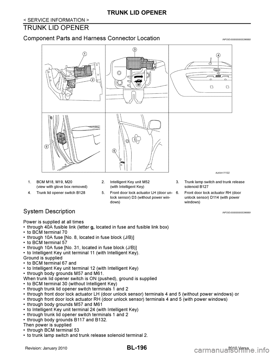
Component Parts and Harness Connector LocationINFOID:0000000005396668
System DescriptionINFOID:0000000005396669
Power is supplied at all times
• through 40A fusible link (letter g, located in fuse and fusible link box)
• to BCM terminal 70
• through 10A fuse [No. 8, located in fuse block (J/B)]
• to BCM terminal 57
• through 10A fuse [No. 31, located in fuse block (J/B)]
• to Intelligent Key unit terminal 11 (with Intelligent Key).
Ground is supplied
• to BCM terminal 67 and
• to Intelligent Key unit terminal 12 (with Intelligent Key)
• through body grounds M57 and M61.
When trunk lid opener switch is ON (pushed), ground is supplied
• to BCM terminal 30 (without Intelligent Key)
• through trunk lid opener switch terminals 1 and 2
• through front door lock actuator LH (door unlock s ensor) terminals 4 and 5 (without power windows) or
• through front door lock actuator RH (door unlock sensor) terminals 4 and 5 (with power windows)
• through body grounds M57 and M61
• to Intelligent Key unit terminal 24 (with Intelligent Key)
• through trunk lid opener switch terminals 1 and 2
• through body grounds B117 and B132.
Then power is supplied
• through BCM terminal 53
• to trunk lamp switch and trunk release solenoid terminal 2.
ALKIA1777ZZ
1. BCM M18, M19, M20
(view with glove box removed) 2. Intelligent Key unit M52
(with Intelligent Key) 3. Trunk lamp switch and trunk release
solenoid B127
4. Trunk lid opener switch B128 5. Front door lock actuator LH (door un- lock sensor) D3 (without power win-
dows)6. Front door lock actuator RH (door
unlock sensor) D1 14 (with power
windows)
Revision: January 20102010 Versa
Page 729 of 3745

BL-220
< SERVICE INFORMATION >
VEHICLE SECURITY (THEFT WARNING) SYSTEM
• to combination meter terminal 27 (security indicator lamp)
• through 40A fusible link (letter g, located in the fuse and fusible link box)
• to BCM terminal 70
• through 10A fuse [No. 8, located in the fuse block (J/B)]
• to BCM terminal 57
• through 10A fuse (No. 28, located in the fuse and fusible link box)
• to horn relay terminal 2
• through 15A fuse (No. 52, located in the IPDM E/R)
• to IPDM E/R internal CPU.
• through 20A fuse (No. 53, located in the IPDM E/R)
• to IPDM E/R internal CPU.
With the ignition switch in the ACC or ON position, power is supplied• through 10A fuse [No. 20, located in the fuse block (J/B)]
• to BCM terminal 11.
With the ignition switch in the ON or START po sition, power is supplied• through 10A fuse [No. 6, located in the fuse block (J/B)]
• to BCM terminal 38.
Ground is supplied• to BCM terminal 67
• through body grounds M57 and M61.
INITIAL CONDITION TO ACTIVATE THE SYSTEM
The operation of the vehicle security system is controlled by the doors and trunk (sedan).
To activate the vehicle security system, BCM must receive signals indicating the ignition switch is OFF, doors
and trunk (sedan) are closed and locked.
When a door or trunk (sedan) is open, BCM terminal 12, 13, 42, 43, 47 or 48 receives a ground signal from
each door or trunk switch. In addition to BCM, when back door is open, the Intelligent Key unit terminal 23
receives a ground signal from back door or trunk (sedan) through BCM terminal 30.
When front door LH is unlocked, BCM terminal 46 receives a signal from terminal 6 of main power window and
door lock/unlock switch.
When front door RH is unlocked, BCM terminal 46 receives a signal from terminal 2 of power window and door
lock/unlock switch RH.
VEHICLE SECURITY SYSTEM ALARM OPERATION
The vehicle security system is triggered by
• Opening a door without using the key, keyfob or Intelligent Key.
• Opening trunk without using the key, keyfob or Intelligent Key (sedan).
The vehicle security system will be tri ggered once the system is in armed phase,
• when BCM receives a ground signal at terminals 12, 13, 47, 48 (front or rear door switch), terminal 42
(sedan, trunk switch) or terminal 43 (hatchback, back door switch).
When the vehicle security system is triggered, ground is supplied intermittently
• from IPDM E/R terminal 45
• to horn relay terminal 1.
The headlamps flash and the horn sounds intermittently.
The alarm automatically turns off after 50 seconds, but will reactivate if the vehicle is tampered with again.
VEHICLE SECURITY SYSTEM DEACTIVATION
To deactivate the vehicle security system, a door or trunk (sedan) must be unlocked with the key, keyfob or
Intelligent Key.
When the key is used to unlock the driver door, BCM terminal 7 receives signal
• from terminal 3 of the front door key cylinder switch LH.
When the key is used to open the trunk (sedan), BCM terminal 41 receives signal
• from terminal 1 of the trunk key cylinder switch.
When the BCM receives an unlock signal from keyfob, In telligent Key, front door key cylinder switch LH or
trunk key cylinder switch (sedan), the vehicle se curity system is deactivated (Disarmed phase).
PANIC ALARM OPERATION
Intelligent Key and remote keyless entry system may or may not operate vehicle security system (horn and
headlamps) as required.
When the vehicle security system is triggered, ground is supplied intermittently
Revision: January 20102010 Versa
Page 779 of 3745

BL-270
< SERVICE INFORMATION >
BODY REPAIR
4. Front pillar inner reinforcement (RH&LH)
5. Lower dash reinforcement
6. 4th crossmember (RH&LH)
7. Front side member rear extension (RH&LH)
8. 3rd crossmember (RH&LH)
9. Front seat outer rear bracket (RH&LH)
10. Front seat inner rear bracket (RH&LH)
11. 2nd crossmember (RH&LH)
12. Front seat outer front bracket (RH&LH)
13. Front seat inner front bracket (RH&LH)
14. Fender bracket (RH&LH)
15. Strut housing assembly RH
16. Cowl top side upper (RH&LH)
17. Front strut housing (RH&LH)
18. Upper torque rod reinforcement
19. Closing plate assembly RH
20. Engine mount reinforcement
21. Strut tower front reinforcement RH
22. Front hoodledge lower RH
23. Frame bracket outer (RH&LH)
24. Front bumper support bracket (RH&LH)
25. Closing plate (RH&LH)
26. Front suspension rear bracket (RH&LH)
27. Front side member outrigger (RH&LH)
28. Front side member assembly (RH&LH)
29. Front side member (RH&LH)
30. Frame bracket (RH&LH)
31. Closing plate assembly LH
32. Hoodledge connector (RH&LH)
33. Radiator core side support (RH&LH)
34. Radiator core support upper (RH&LH)
35. Hoodledge upper (RH&LH)
36. Hoodledge reinforcement assembly (RH&LH)
37. Dash side (RH&LH)
38. Dash side assembly (RH& LH)
39. Front floor reinforcement (RH&LH)
40. Front floor front (RH&LH)
41. Front floor center
42. Rear seat crossmember
43. Rear center crossmember
44. Rear seat upper crossmember
45. Rear side member (RH&LH)
46. Sill inner extension (RH&LH)
47. Rear side member extension (RH&LH)
48. Rear side member assembly (RH & LH)
49. Rear floor front
50. Rear floor front assembly
51. Rear floor side (RH&LH)
52. Rear floor rear
Revision: January 20102010 Versa
Page 781 of 3745

BL-272
< SERVICE INFORMATION >
BODY REPAIR
6. 1st roof rail assembly
7. Front roof rail assembly
8. Sun roof assembly
9. Front roof rail assembly (if equipped with sunroof)
10. Roof side rail reinforcement (RH & LH)
11. Inner center pillar (RH & LH)
12. Hood assembly
13. Center pillar reinforcement (RH & LH)
14. Front pillar inner (RH & LH)
15. Front pillar upper reinforcement (RH & LH)
16. Front pillar lower reinforcement (RH & LH)
17. Fender (RH & LH)
18. Side body (RH & LH)
19. Side body assembly (RH & LH)
20. Outer sill (RH & LH)
21. Outer sill reinforcement (RH & LH)
22. Front door assembly (RH & LH)
23. Outer front door panel (RH & LH)
24. Outer rear door panel (RH & LH)
25. Rear door assembly (RH & LH)
26. Rear fender (RH & LH)
27. Rear fender assembly (RH & LH)
28. Rear fender corner (RH & LH)
29. Rear fender extension (RH & LH)
30. Rear combination lamp base (RH & LH)
31. Rear pillar inner reinforcement (RH & LH)
32. Rear wheel housing outer (RH & LH)
33. Rear wheel housing inner (RH & LH)
34. Rear spring base assembly (RH & LH)
35. Rear seatback hinge bracket (RH & LH)
36. Rear seatback catch bracket (RH & LH)
37. Rear pillar inner (RH & LH)
38. Rear roof rail reinforcement (RH & LH)
39. Rear roof rail brace (RH & LH)
40. Rear panel
41. Rear bumper fascia lower bracket
42. Rear bumper fascia upper bracket
43. Rear bumper fascia center bracket
44. Rear panel assembly
45. Back door assembly
Revision: January 20102010 Versa
Page 783 of 3745

BL-274
< SERVICE INFORMATION >
BODY REPAIR
7. Front roof rail assembly
8. Sun roof assembly
9. Front roof rail assembly (if equipped with sunroof)
10. Roof side rail reinforcement (RH & LH)
11. Inner center pillar (RH & LH)
12. Hood assembly
13. Center pillar reinforcement (RH & LH)
14. Front pillar inner (RH & LH)
15. Front pillar upper reinforcement (RH & LH)
16. Front pillar lower reinforcement (RH & LH)
17. Fender (RH & LH)
18. Side body (RH & LH)
19. Side body assembly (RH & LH)
20. Outer sill (RH & LH)
21. Outer sill reinforcement (RH & LH)
22. Front door assembly (RH & LH)
23. Outer front door panel (RH & LH)
24. Outer rear door panel (RH & LH)
25. Rear door assembly (RH & LH)
26. Rear fender (RH & LH)
27. Rear fender corner (RH & LH)
28. Rear combination lamp base (RH & LH)
29. Rear wheel housing front extension (RH & LH)
30. Rear wheel housing outer (RH & LH)
31. Rear pillar inner reinforcement (RH & LH)
32. Rear body side inner (RH & LH)
33. Rear wheel housing inner (RH & LH)
34. Rear panel assembly
35. Rear bumper fascia upper bracket
36. Rear bumper fascia center bracket
37. Trunk lid assembly
38. Parcel shelf side (RH & LH)
39. Parcel shelf assembly
40. Rear waist panel
41. Rear bumper fascia lower bracket
Corrosion ProtectionINFOID:0000000005396720
DESCRIPTION
To provide improved corrosion prevention, the following anti-corrosive measures have been implemented in
NISSAN production plants. When repairing or replacing body panels, it is necessary to use the same anti-cor-
rosive measures.
ANTI-CORROSIVE PRECOATED STEEL (GALVANNEALED STEEL)
Revision: January 20102010 Versa
Page 816 of 3745
BODY REPAIRBL-307
< SERVICE INFORMATION >
C
DE
F
G H
J
K L
M A
B
BL
N
O P
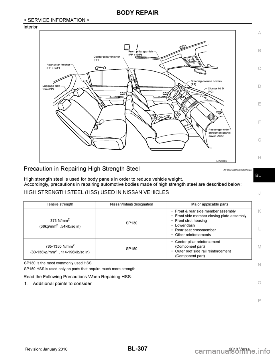
Interior
Precaution in Repairing High Strength SteelINFOID:0000000005396725
High strength steel is used for body panels in order to reduce vehicle weight.
Accordingly, precautions in repairing automotive bodies made of high strength steel are described below:
HIGH STRENGTH STEEL (HSS) USED IN NISSAN VEHICLES
SP130 is the most commonly used HSS.
SP150 HSS is used only on parts that require much more strength.
Read the Following Precautions When Repairing HSS:
1. Additional points to consider
LIIA2588E
Tensile strength
Nissan/Infiniti designation Major applicable parts
373 N/mm
2
(38kg/mm2 ,54klb/sq in) SP130• Front & rear side member assembly
• Front side member closing plate assembly
• Front strut housing
• Lower dash
• Rear seat crossmember
• Other reinforcements
785-1350 N/mm
2
(80-138kg/mm2 , 114-196klb/sq in) SP150• Center pillar reinforcement
(Component part)
• Outer roof side rail reinforcement (Component part)
Revision: January 20102010 Versa
Page 821 of 3745
BL-312
< SERVICE INFORMATION >
BODY REPAIR
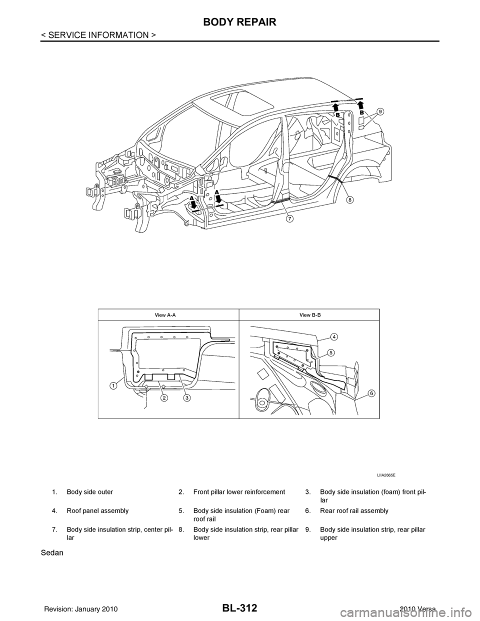
Sedan
1. Body side outer2. Front pillar lower reinforcement 3. Body side insulation (foam) front pil-
lar
4. Roof panel assembly 5. Body side insulation (Foam) rear
roof rail 6. Rear roof rail assembly
7. Body side insulation strip, center pil- lar 8. Body side insulation strip, rear pillar
lower 9. Body side insulation strip, rear pillar
upper
LIIA2665E
Revision: January 20102010 Versa
Page 822 of 3745
BODY REPAIRBL-313
< SERVICE INFORMATION >
C
DE
F
G H
J
K L
M A
B
BL
N
O P
Replacement OperationINFOID:0000000005396727
DESCRIPTION
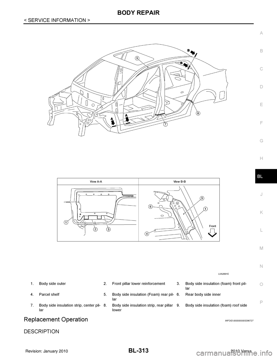
1. Body side outer 2. Front pillar lower reinforcement 3. Body side insulation (foam) front pil-
lar
4. Parcel shelf 5. Body side insulation (Foam) rear pil-
lar 6. Rear body side inner
7. Body side insulation strip, center pil- lar 8. Body side insulation strip, rear pillar
lower 9. Body side insulation (foam) roof side
LIIA2891E
Revision: January 20102010 Versa