2010 NISSAN TIIDA fluid
[x] Cancel search: fluidPage 3427 of 3745

PG-44
< SERVICE INFORMATION >
HARNESS
Refer to "ENGINE ROOM HARNESS (LH VIEW)" for continuation of engine room harness.
G2 E1 GR/5 : Front wiper motor F2 E33 B/26 : ABS actuator and electric unit (control unit)
C3 E2 B/2 : Front and rear washer motor E2 E37 B/5 : Daytime light relay 1
F5 E4 Y/2 : Crash zone sensor D2 E38 L/5 : Daytime light relay 2
E4 E17 B/3 : Refrigerant pressure sensor E2 E41 — : Ground (ABS)
D2 E24 — : Engine ground C3 E50 W/2 : Washer fluid level switch
C3 E26 B/3 : Front combination lamp RH (headlamp) D1 E52 B/2 : Front wheel sensor RH
C4 E28 B/2 : Front fog lamp RH D2 E54 B/2 : Front combination lamp RH (parking)
D3 E30 B/2 : Front combination lamp RH (turn signal)
Revision: January 20102010 Versa
Page 3442 of 3745

HARNESSPG-59
< SERVICE INFORMATION >
C
DE
F
G H
I
J
L
M A
B
PG
N
O P
Wiring Diagram Codes (Cell Codes)INFOID:0000000005395367
Use the chart below to find out what each wiring diagram code stands for.
Refer to the wiring diagram code in the alphabetical index to find the location (page number) of each wiring
diagram.
D4 D405 W/4 : Back door lock assembly C2 D413 B/1 : Rear window defogger (-)
D4 D406 W/2 : Back door request switch F3 D414 — : Body ground
E2 D407 W/2 : High mounted stop lamp
Code Section Wiring Diagram Name
ABS BRC Anti-lock Brake System
A/C,M MTC Manual Air Conditioner
APPS1 EC Accelerator Pedal Position Sensor
A/F EC Air Fuel Ratio Sensor 1
A/FH EC Air Fuel Ratio Sensor 1 Heater
APPS2 EC Accelerator Pedal Position Sensor
APPS3 EC Accelerator Pedal Position Sensor
ASC/BS EC ASCD Brake Switch
ASC/SW EC ASCD Steering Switch
ASCBOF EC ASCD Brake Switch
ASCIND EC ASCD Indicator
AT/IND DI A/T Indicator Lamp
AUDIO AV Audio
BACK/L LT Back-up Lamp
BA/FTS AT A/T Fluid Temperature Sensor and TCM Power Supply
B/DOOR BL Back Door Opener
BRK/SW EC Brake Switch
CAN AT CAN Communication Line
CAN CVT CAN Communication Line
CAN EC CAN Communication Line
CAN LAN CAN System
CHARGE SC Charging System
CHIME DI Warning Chime
COOL/F EC Cooling Fan Control
COMBSW LT Combination Switch
COMM AV Audio Visual Communication System
CVTIND DI CVT Indicator Lamp
D/LOCK BL Power Door Lock
DEF GW Rear Window Defogger
DTRL LT Headlamp - Wi th Daytime Light System
ECTS EC Engine Coolant Temperature Sensor
ENGSS AT Engine Speed Signal
EPS STC Electronic Controlled Power Steering
ETC1 EC Electric Throttle Control Function
ETC2 EC Throttle Control Motor Relay
ETC3 EC Throttle Control Motor
F/FOG LT Front Fog Lamp
F/PUMP EC Fuel Pump
FTS AT A/T Fluid Temperature Sensor
FTS CVT CVT Fluid Temperature Sensor Circuit
FTTS EC Fuel Tank Temperature Sensor
FUEL EC Fuel Ignition System Function
Revision: January 20102010 Versa
Page 3526 of 3745
RSU-12
< SERVICE INFORMATION >
REAR SUSPENSION BEAM
REAR SUSPENSION BEAM
Removal and InstallationINFOID:0000000005397082
REMOVAL
1. Remove wheel and tire using power tool.
2. Separate parking brake rear cable from rear drum brake and rear suspension beam. Refer to PB-5, "
On-
Vehicle Service".
3. Remove wheel sensor and wheel sensor harness from wheel hub and bearing assembly and rear suspen-
sion beam. Refer to BRC-34, "
Removal and Installation".
4. Remove lock plate and separate brake tube from brake hose. Refer to BR-12, "
Rear Brake Tube and Hose".
5. Remove wheel hub and bearing assembly and back plate. Refer to RAX-6, "
On-Vehicle Inspection and Service".
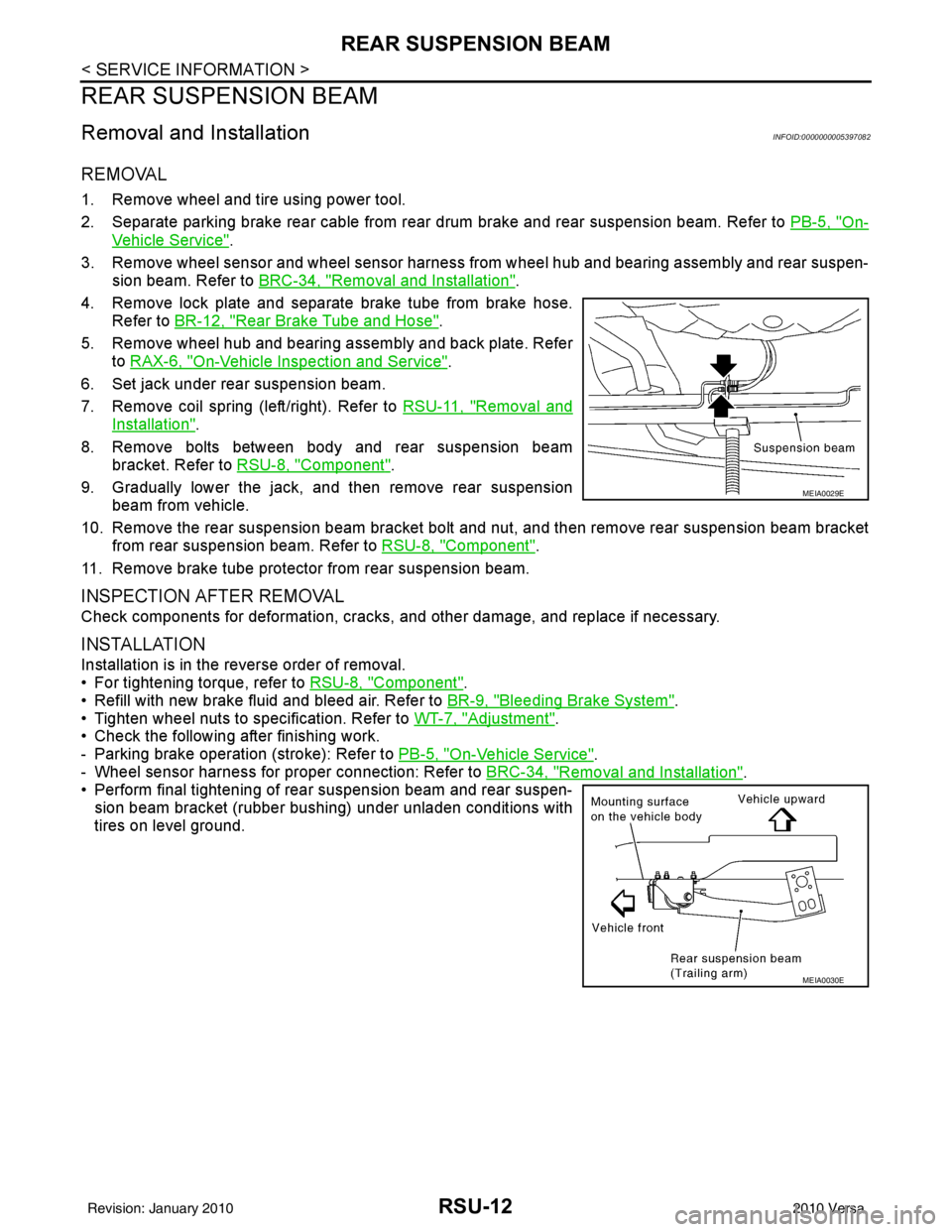
6. Set jack under rear suspension beam.
7. Remove coil spring (left/right). Refer to RSU-11, "
Removal and
Installation".
8. Remove bolts between body and rear suspension beam bracket. Refer to RSU-8, "
Component".
9. Gradually lower the jack, and then remove rear suspension beam from vehicle.
10. Remove the rear suspension beam bracket bolt and nut, and then remove rear suspension beam bracket
from rear suspension beam. Refer to RSU-8, "
Component".
11. Remove brake tube protector from rear suspension beam.
INSPECTION AFTER REMOVAL
Check components for deformation, cracks, and other damage, and replace if necessary.
INSTALLATION
Installation is in the reverse order of removal.
• For tightening torque, refer to RSU-8, "
Component".
• Refill with new brake fluid and bleed air. Refer to BR-9, "
Bleeding Brake System".
• Tighten wheel nuts to specification. Refer to WT-7, "
Adjustment".
• Check the following after finishing work.
- Parking brake operation (stroke): Refer to PB-5, "
On-Vehicle Service".
- Wheel sensor harness for proper connection: Refer to BRC-34, "
Removal and Installation".
• Perform final tightening of rear suspension beam and rear suspen-
sion beam bracket (rubber bushing) under unladen conditions with
tires on level ground.
MEIA0029E
MEIA0030E
Revision: January 20102010 Versa
Page 3544 of 3745
BATTERYSC-5
< SERVICE INFORMATION >
C
DE
F
G H
I
J
L
M A
B
SC
N
O P
BATTERY
How to Handle BatteryINFOID:0000000005394857
CAUTION:
• If it becomes necessary to start the engine with a booster battery and jumper cables, use a 12-volt
booster battery.
• After connecting battery cables, ensure that they are tightly clamped to battery terminals for good
contact.
• Never add distilled water through the hole used to check specific gravity.
METHODS OF PREVENTING OVER-DISCHARGE
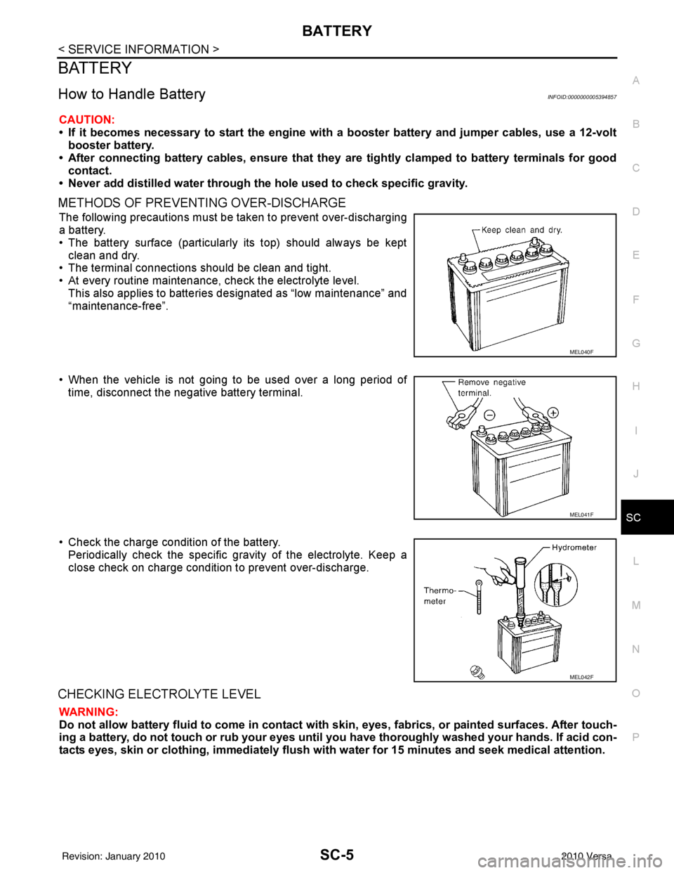
The following precautions must be taken to prevent over-discharging
a battery.
• The battery surface (particularly its top) should always be kept
clean and dry.
• The terminal connections should be clean and tight.
• At every routine maintenance, check the electrolyte level.
This also applies to batteries designated as “low maintenance” and
“maintenance-free”.
• When the vehicle is not going to be used over a long period of time, disconnect the negative battery terminal.
• Check the charge condition of the battery. Periodically check the specific gr avity of the electrolyte. Keep a
close check on charge condition to prevent over-discharge.
CHECKING ELECTROLYTE LEVEL
WARNING:
Do not allow battery fluid to come in contact with skin, eyes, fabrics, or painted surfaces. After touch-
ing a battery, do not touch or rub your eyes until yo u have thoroughly washed your hands. If acid con-
tacts eyes, skin or clothing, imme diately flush with water for 15 minutes and seek medical attention.
MEL040F
MEL041F
MEL042F
Revision: January 20102010 Versa
Page 3726 of 3745
FRONT WIPER AND WASHER SYSTEMWW-21
< SERVICE INFORMATION >
C
DE
F
G H
I
J
L
M A
B
WW
N
O P
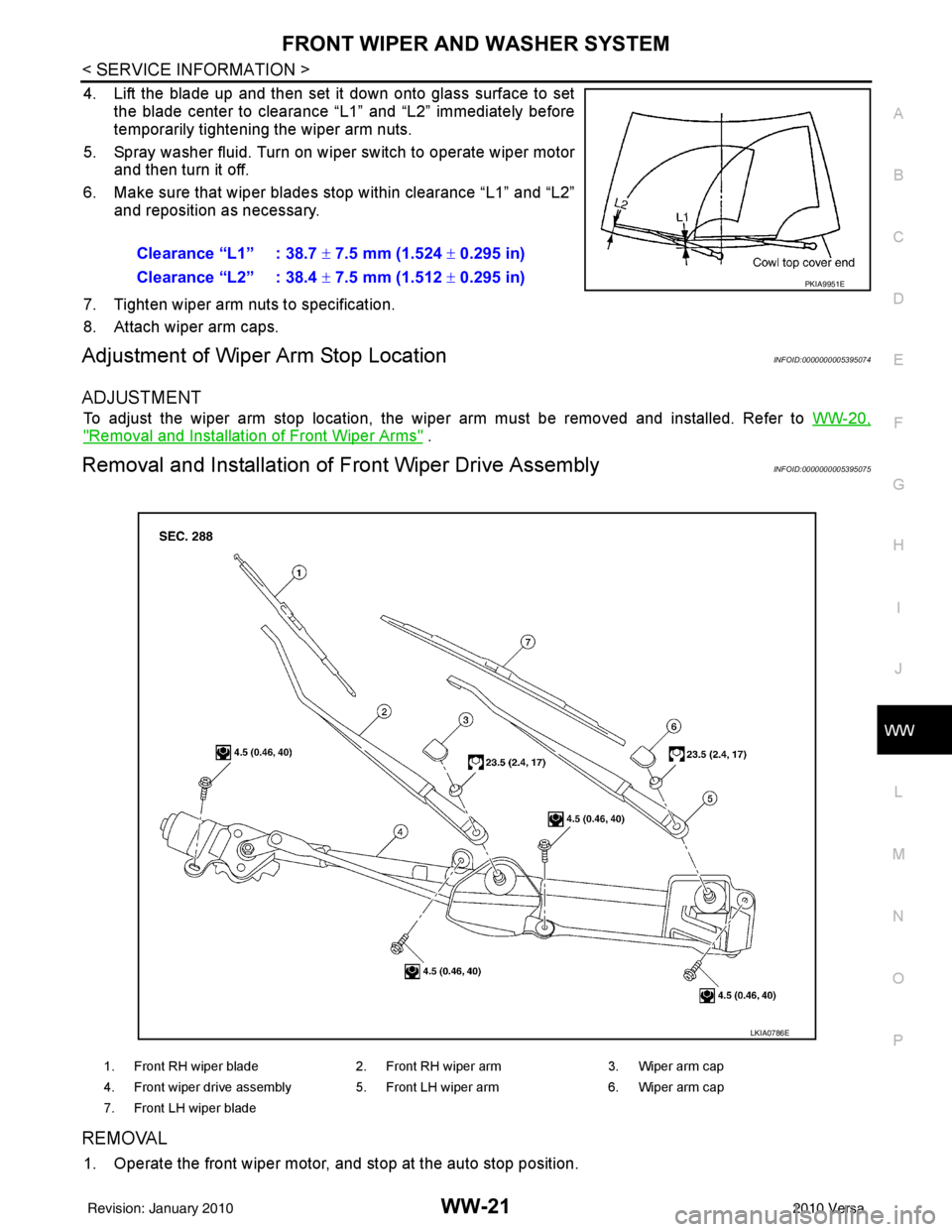
4. Lift the blade up and then set it down onto glass surface to set the blade center to clearance “L1” and “L2” immediately before
temporarily tightening the wiper arm nuts.
5. Spray washer fluid. Turn on wiper switch to operate wiper motor and then turn it off.
6. Make sure that wiper blades stop within clearance “L1” and “L2” and reposition as necessary.
7. Tighten wiper arm nuts to specification.
8. Attach wiper arm caps.
Adjustment of Wiper Arm Stop LocationINFOID:0000000005395074
ADJUSTMENT
To adjust the wiper arm stop location, the wiper arm must be removed and installed. Refer to WW-20,
"Removal and Installation of Front Wiper Arms" .
Removal and Installation of Front Wiper Drive AssemblyINFOID:0000000005395075
REMOVAL
1. Operate the front wiper motor, and stop at the auto stop position.Clearance “L1” : 38.7
± 7.5 mm (1.524 ± 0.295 in)
Clearance “L2” : 38.4 ± 7.5 mm (1.512 ± 0.295 in)
PKIA9951E
1. Front RH wiper blade 2. Front RH wiper arm 3. Wiper arm cap
4. Front wiper drive assembly 5. Front LH wiper arm 6. Wiper arm cap
7. Front LH wiper blade
LKIA0786E
Revision: January 20102010 Versa
Page 3729 of 3745
WW-24
< SERVICE INFORMATION >
FRONT WIPER AND WASHER SYSTEM
Removal and Installation of Fr ont Wiper and Washer Switch
INFOID:0000000005395080
REMOVAL
1. Remove the steering column cover. Refer to IP-11 .
2. Disconnect the wiper and washer switch connector.
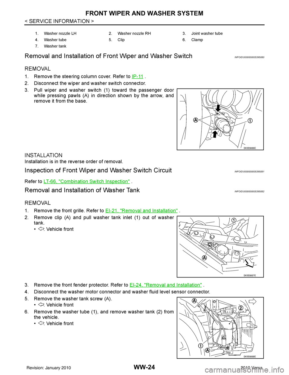
3. Pull wiper and washer switch (1) toward the passenger door while pressing pawls (A) in direction shown by the arrow, and
remove it from the base.
INSTALLATION
Installation is in the reverse order of removal.
Inspection of Front Wiper and Washer Switch CircuitINFOID:0000000005395081
Refer to LT-66, "Combination Switch Inspection" .
Removal and Installation of Washer TankINFOID:0000000005395082
REMOVAL
1. Remove the front grille. Refer to EI-21, "Removal and Installation" .
2. Remove clip (A) and pull washer tank inlet (1) out of washer tank.
• : Vehicle front
3. Remove the front fender protector. Refer to EI-24, "
Removal and Installation" .
4. Disconnect the washer motor connector and washer fluid level sensor connector.
5. Remove the washer tank screw (A). • : Vehicle front
6. Remove the washer tube (1), and remove washer tank (2) from the vehicle.
• : Vehicle front
1. Washer nozzle LH 2. Washer nozzle RH3. Joint washer tube
4. Washer tube 5. Clip6. Clamp
7. Washer tank
SKIB5666E
SKIB5667E
SKIB5668E
Revision: January 20102010 Versa
Page 3740 of 3745
REAR WIPER AND WASHER SYSTEMWW-35
< SERVICE INFORMATION >
C
DE
F
G H
I
J
L
M A
B
WW
N
O P
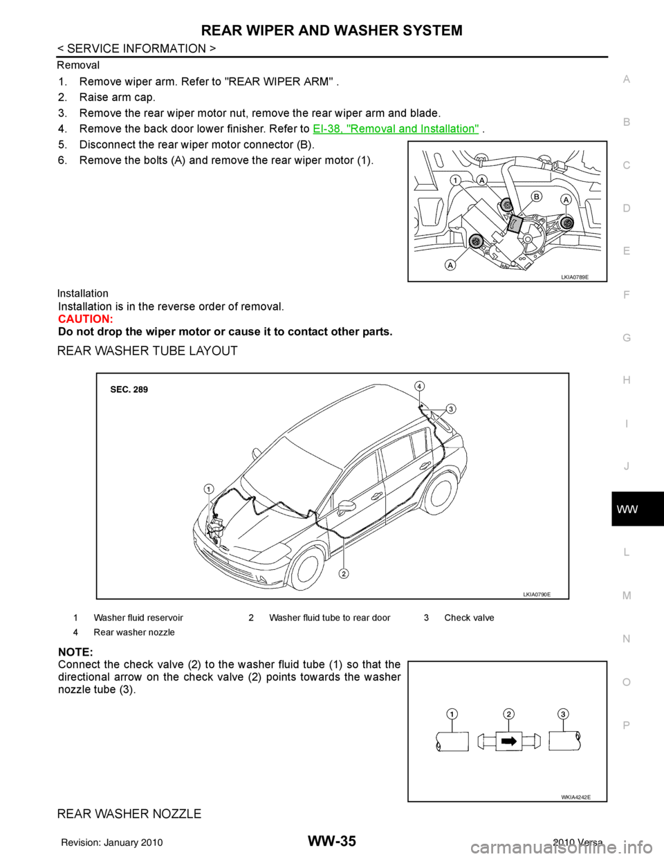
Removal
1. Remove wiper arm. Refer to "REAR WIPER ARM" .
2. Raise arm cap.
3. Remove the rear wiper motor nut, remove the rear wiper arm and blade.
4. Remove the back door lower finisher. Refer to
EI-38, "
Removal and Installation" .
5. Disconnect the rear wiper motor connector (B).
6. Remove the bolts (A) and remove the rear wiper motor (1).
Installation
Installation is in the reverse order of removal.
CAUTION:
Do not drop the wiper motor or cause it to contact other parts.
REAR WASHER TUBE LAYOUT
NOTE:
Connect the check valve (2) to the washer fluid tube (1) so that the
directional arrow on the check valve (2) points towards the washer
nozzle tube (3).
REAR WASHER NOZZLE
LKIA0789E
1 Washer fluid reservoir 2 Washer fluid tube to rear door 3 Check valve
4 Rear washer nozzle
LKIA0790E
WKIA4242E
Revision: January 20102010 Versa
Page 3741 of 3745
WW-36
< SERVICE INFORMATION >
REAR WIPER AND WASHER SYSTEM
Removal
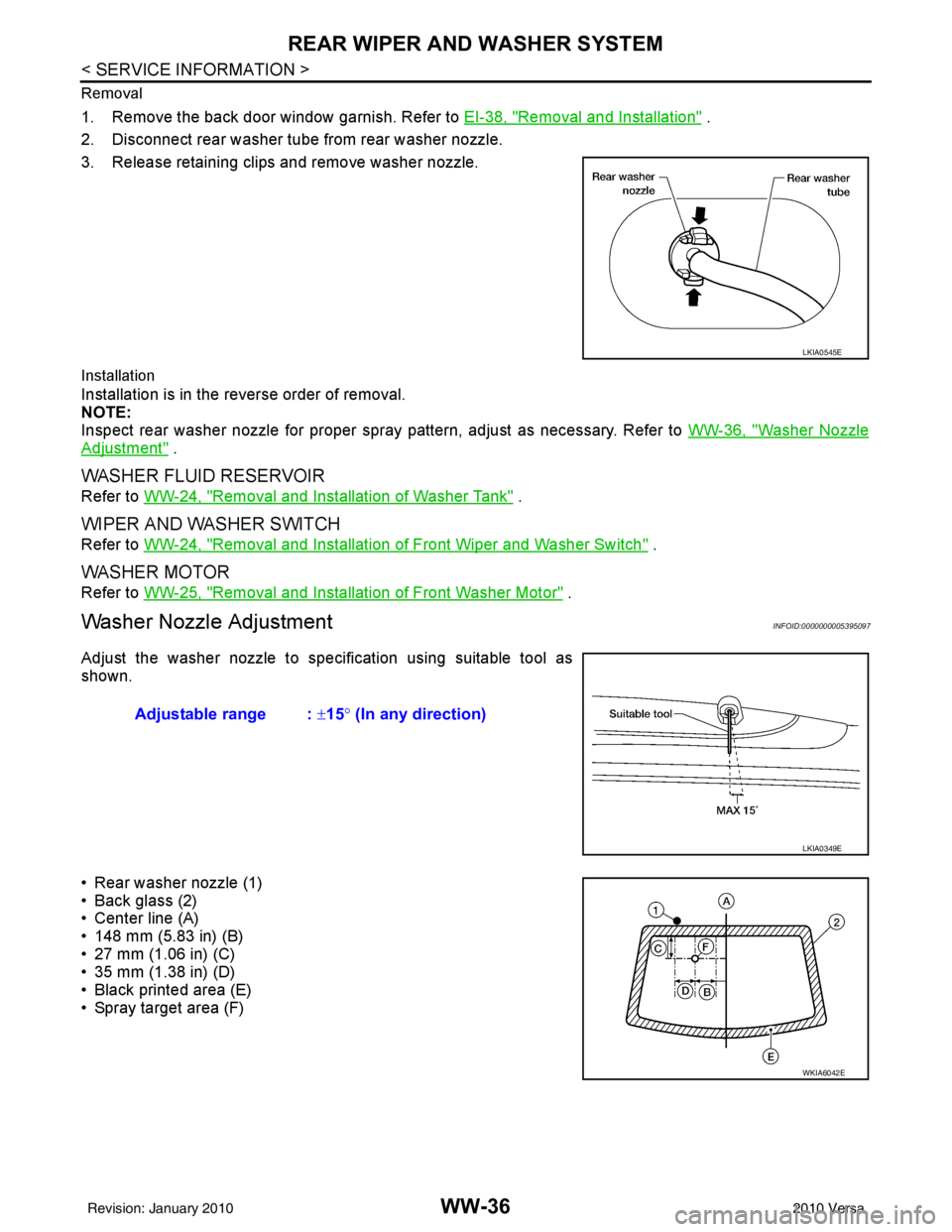
1. Remove the back door window garnish. Refer to EI-38, "Removal and Installation" .
2. Disconnect rear washer tube from rear washer nozzle.
3. Release retaining clips and remove washer nozzle.
Installation
Installation is in the reverse order of removal.
NOTE:
Inspect rear washer nozzle for proper spray pattern, adjust as necessary. Refer to WW-36, "
Washer Nozzle
Adjustment" .
WASHER FLUID RESERVOIR
Refer to WW-24, "Removal and Installation of Washer Tank" .
WIPER AND WASHER SWITCH
Refer to WW-24, "Removal and Installation of Front Wiper and Washer Switch" .
WASHER MOTOR
Refer to WW-25, "Removal and Installation of Front Washer Motor" .
Washer Nozzle AdjustmentINFOID:0000000005395097
Adjust the washer nozzle to specification using suitable tool as
shown.
• Rear washer nozzle (1)
• Back glass (2)
• Center line (A)
• 148 mm (5.83 in) (B)
• 27 mm (1.06 in) (C)
• 35 mm (1.38 in) (D)
• Black printed area (E)
• Spray target area (F)
LKIA0545E
Adjustable range : ±15° (In any direction)
LKIA0349E
WKIA6042E
Revision: January 20102010 Versa