Page 648 of 3745

INTELLIGENT KEY SYSTEMBL-139
< SERVICE INFORMATION >
C
DE
F
G H
J
K L
M A
B
BL
N
O P
OK or NG
OK >> Trunk opener request switch circuit is OK.
NG >> GO TO 2
2.CHECK TRUNK OPENER REQUEST SWITCH CIRCUIT
1. Turn ignition switch OFF.
2. Disconnect Intelligent Key unit and trunk opener request switch connector.
3. Check continuity between Intelligent Key unit connector (A) M52 terminal 29 and trunk opener request switch connector (B) B129 terminal 1.
4. Check continuity between Intelligent Key unit connector (A) M52 terminal 29 and ground.
OK or NG
OK >> GO TO 3
NG >> Repair or replace harness between Intelligent Key unit and trunk opener request switch.
3.CHECK TRUNK OPENER REQUEST SWITCH OPERATION
Check continuity of trunk opener request switch.
OK or NG
OK >> GO TO 4
NG >> Replace trunk opener request switch.
4.CHECK TRUNK OPENER REQUEST SWITCH GROUND CIRCUIT
Check continuity between trunk opener request switch connector B129 terminal 2 and ground.
Te r m i n a l s
Trunk opener
request switch condition Voltage (V)
(Approx.)
(+)
(–)
Intelligent Key
unit connector Te r m i n a l
M52 29Ground Pressed
0
Released 5
PIIB6617E
AB
Continuity
Intelligent Key
unit connector Te r m i n a l Trunk opener re-
quest switch con-
nector Te r m i n a l
M52 29B129 1Yes
A GroundContinuity
Intelligent Key unit
connector Te r m i n a l
M52 29 No
PIIB6618E
Te r m i n a l
trunk opener request
switch condition Continuity
trunk opener request switch
12 Pressed
Yes
Released No
PIIB6336E
Revision: January 20102010 Versa
Page 687 of 3745

BL-178
< SERVICE INFORMATION >
BACK DOOR LOCK
435R Back door switch Input OFFON (open) 0V
OFF (closed)
Battery voltage
44
5LG Rear wiper auto stop Input ON Rear wiper operating 0
Rear wiper stopped
Battery
45
7GR Lock switch Input OFFON (lock)
0V
OFF Battery voltage
46
7L Unlock switch Input OFFON (unlock)
0V
OFF Battery voltage
47 BR Front door switch LH Input OFF ON (open)
0V
OFF (closed) Battery voltage
48 O Rear door switch LH Input OFF ON (open)
0V
OFF (closed) Battery voltage
49 P Luggage room lamp Output OFF Any door open (ON)
0V
All doors closed (OFF) Battery voltage
50 SB A/C indicator Output ONA/C OFF
0
A/C ON Battery voltage
53
5R Back door lock assem-
bly (actuator)
Output OFF Back door (open)
Battery voltage
53
6R Trunk lamp switch and
trunk release solenoid Output OFF Trunk lid (open)
Battery voltage
55
5V Rear wiper motor out-
put
Output ONOFF
0
ON Battery voltage
56 R Battery saver output Output OFF
30 minutes after ignition
switch is turned OFF 0V
ON — Battery voltage
57 LG Battery power supply Input OFF —Battery voltage
59
7G Front door lock actua-
tor LH (unlock) Output OFFOFF (neutral)
0V
ON (unlock) Battery voltage
60 V Turn signal (left) Output ON Turn left ON
61 W Turn signal (right) Output ON Turn right ON
63 BR Interior room lamp Output OFF Any door
switchON (open)
0V
OFF (closed) Battery voltage
Te r m i n a l
Wire
color Signal name Signal
input/
output Measuring condition
Reference value or waveform
(Approx.)
Ignition
switch Operation or condition
SKIA3009J
SKIA3009J
Revision: January 20102010 Versa
Page 699 of 3745

BL-190
< SERVICE INFORMATION >
BACK DOOR LOCK
Check continuity between back door opener switch connector termi-
nal 2 and ground.
OK or NG
OK >> GO TO 5
NG >> Repair or replace harness.
5.CHECK INTELLIGENT KEY UNIT OUTPUT SIGNAL
1. Connect Intelligent Key unit connector.
2. Check voltage between Intelligent Key unit connector M52 terminal 24 and ground.
OK or NG
OK >> Check the condition of harness and connector.
NG >> Replace Intelligent Key unit. Refer to BL-158, "
Removal
and Installation of Intelligent Key Unit".
Check Back Door Lock Asse mbly (Actuator) CircuitINFOID:0000000005396662
1.CHECK BACK DOOR LOCK ASSE MBLY (ACTUATOR) FUNCTION
With CONSULT-III
Check the operation with (“TRUNK/BACK DOOR”) in the ACTIVE TEST.
YES or NO
YES >> Back door lock assembly (actuator) is OK.
NO >> GO TO 2
2.CHECK BACK DOOR LOCK ASSEMB LY (ACTUATOR) POWER SUPPLY
1. Turn ignition switch OFF.
2. Insure both front door lock knobs are turned to the UNLOCK position.
3. Disconnect back door lock assembly (actuator) connector.
4. Check voltage between back door lock assembly (actuator) connector D405 terminal 1 and ground.
Back door opener switch connector Te r m i n a l
GroundContinuity
D408 2 Yes
PIIB6472E
Te r m i n a l s
Voltage (V)(Approx.)
(+)
(–)
Intelligent Key unit
connector Te r m i n a l
M52 24Ground 5
WIIA1279E
Does back door actuator system operate normally?
Te r m i n a l s
ConditionVoltage (V)
(Approx.)
(+)
(–)
Back door
lock as-
sembly (ac-
tuator)
connector Te r m i n a l
D405 1 Ground Back door
opener switch Pushed 0
↓
Battery voltage ↓0
Released 0
WIIA1275E
Revision: January 20102010 Versa
Page 702 of 3745
TRUNK LIDBL-193
< SERVICE INFORMATION >
C
DE
F
G H
J
K L
M A
B
BL
N
O P
TRUNK LID
Fitting AdjustmentINFOID:0000000005396664
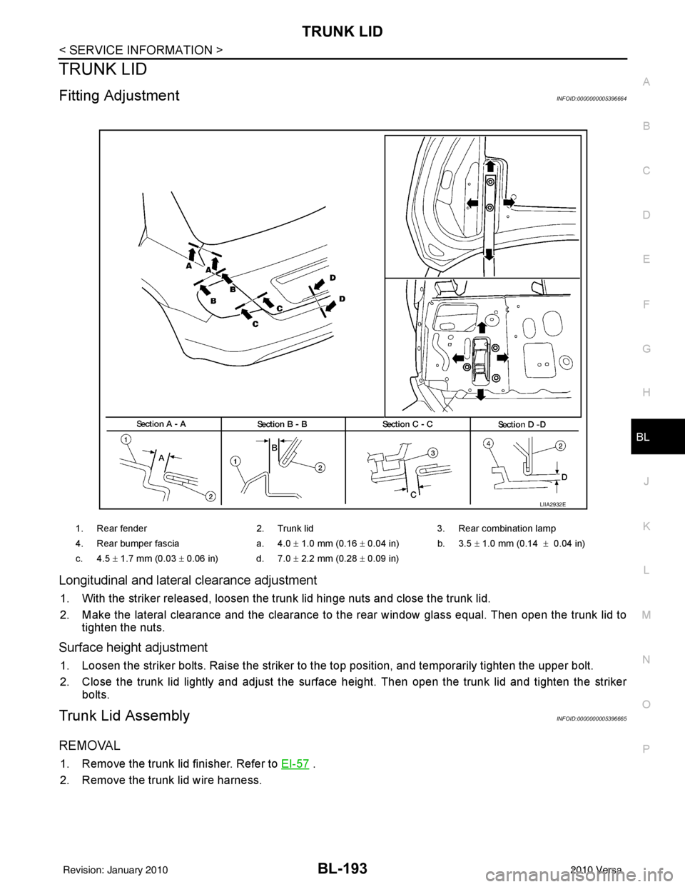
Longitudinal and latera l clearance adjustment
1. With the striker released, loosen the trunk lid hinge nuts and close the trunk lid.
2. Make the lateral clearance and the clearance to the rear window glass equal. Then open the trunk lid to
tighten the nuts.
Surface height adjustment
1. Loosen the striker bolts. Raise the striker to t he top position, and temporarily tighten the upper bolt.
2. Close the trunk lid lightly and adjust the surface height. Then open the trunk lid and tighten the striker bolts.
Trunk Lid AssemblyINFOID:0000000005396665
REMOVAL
1. Remove the trunk lid finisher. Refer to EI-57 .
2. Remove the trunk lid wire harness.
1. Rear fender 2. Trunk lid3. Rear combination lamp
4. Rear bumper fascia a. 4.0 ± 1.0 mm (0.16 ± 0.04 in) b. 3.5 ± 1.0 mm (0.14 ± 0.04 in)
c. 4.5 ± 1.7 mm (0.03 ± 0.06 in) d. 7.0 ± 2.2 mm (0.28 ± 0.09 in)
LIIA2932E
Revision: January 20102010 Versa
Page 703 of 3745
BL-194
< SERVICE INFORMATION >
TRUNK LID
3. Remove the nuts (a) and the trunk lid assembly (1).
INSTALLATION
Installation is in the reverse order of removal.
CAUTION:
After installing, apply touch-up paint (body color) to the head of the hinge nuts.
Trunk Lid LockINFOID:0000000005396666
REMOVAL
1. Remove the trunk lid finisher. Refer to EI-57.
2. If equipped, disconnect the trunk lid lock cylinder rod.
3. Remove the release cable.
4. Disconnect the electrical connector (a), remove the bolts (b) and the trunk lid lock (1).
INSTALLATION
Installation is in the reverse order of removal.
Trunk Lid StrikerINFOID:0000000005396667
REMOVAL
1. Remove the trunk rear plate and trunk rear finisher. Refer to EI-57.
2. Remove the bolts, disconnect the electrical connector and remove the trunk lock actuator.
3. Remove the bolt and disconnect the trunk lid release cable.
LIIA2933E
LIIA2935E
Revision: January 20102010 Versa
Page 705 of 3745
BL-196
< SERVICE INFORMATION >
TRUNK LID OPENER
TRUNK LID OPENER
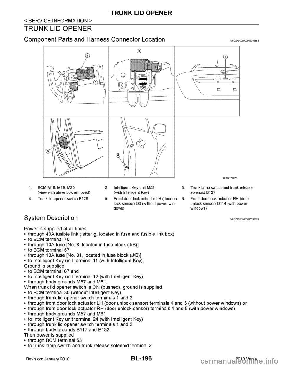
Component Parts and Harness Connector LocationINFOID:0000000005396668
System DescriptionINFOID:0000000005396669
Power is supplied at all times
• through 40A fusible link (letter g, located in fuse and fusible link box)
• to BCM terminal 70
• through 10A fuse [No. 8, located in fuse block (J/B)]
• to BCM terminal 57
• through 10A fuse [No. 31, located in fuse block (J/B)]
• to Intelligent Key unit terminal 11 (with Intelligent Key).
Ground is supplied
• to BCM terminal 67 and
• to Intelligent Key unit terminal 12 (with Intelligent Key)
• through body grounds M57 and M61.
When trunk lid opener switch is ON (pushed), ground is supplied
• to BCM terminal 30 (without Intelligent Key)
• through trunk lid opener switch terminals 1 and 2
• through front door lock actuator LH (door unlock s ensor) terminals 4 and 5 (without power windows) or
• through front door lock actuator RH (door unlock sensor) terminals 4 and 5 (with power windows)
• through body grounds M57 and M61
• to Intelligent Key unit terminal 24 (with Intelligent Key)
• through trunk lid opener switch terminals 1 and 2
• through body grounds B117 and B132.
Then power is supplied
• through BCM terminal 53
• to trunk lamp switch and trunk release solenoid terminal 2.
ALKIA1777ZZ
1. BCM M18, M19, M20
(view with glove box removed) 2. Intelligent Key unit M52
(with Intelligent Key) 3. Trunk lamp switch and trunk release
solenoid B127
4. Trunk lid opener switch B128 5. Front door lock actuator LH (door un- lock sensor) D3 (without power win-
dows)6. Front door lock actuator RH (door
unlock sensor) D1 14 (with power
windows)
Revision: January 20102010 Versa
Page 706 of 3745
TRUNK LID OPENERBL-197
< SERVICE INFORMATION >
C
DE
F
G H
J
K L
M A
B
BL
N
O P
Ground is supplied
• to trunk lamp switch and trunk release solenoid terminal 1
• through body grounds B117 and B132.
Then BCM operates trunk lamp switch and trunk release solenoid.
Wiring Diagram - TLID -INFOID:0000000005396670
WITHOUT INTELLIGENT KEY SYSTEM
ABKWA0691GB
Revision: January 20102010 Versa
Page 711 of 3745

BL-202
< SERVICE INFORMATION >
TRUNK LID OPENER
435R Back door switch Input OFFON (open) 0V
OFF (closed)
Battery voltage
44
5LG Rear wiper auto stop Input ON Rear wiper operating 0
Rear wiper stopped
Battery
45
7GR Lock switch Input OFFON (lock)
0V
OFF Battery voltage
46
7L Unlock switch Input OFFON (unlock)
0V
OFF Battery voltage
47 BR Front door switch LH Input OFF ON (open)
0V
OFF (closed) Battery voltage
48 O Rear door switch LH Input OFF ON (open)
0V
OFF (closed) Battery voltage
49 P Luggage room lamp Output OFF Any door open (ON)
0V
All doors closed (OFF) Battery voltage
50 SB A/C indicator Output ONA/C OFF
0
A/C ON Battery voltage
53
5R Back door lock assem-
bly (actuator)
Output OFF Back door (open)
Battery voltage
53
6R Trunk lamp switch and
trunk release solenoid Output OFF Trunk lid (open)
Battery voltage
55
5V Rear wiper motor out-
put
Output ONOFF
0
ON Battery voltage
56 R Battery saver output Output OFF
30 minutes after ignition
switch is turned OFF 0V
ON — Battery voltage
57 LG Battery power supply Input OFF —Battery voltage
59
7G Front door lock actua-
tor LH (unlock) Output OFFOFF (neutral)
0V
ON (unlock) Battery voltage
60 V Turn signal (left) Output ON Turn left ON
61 W Turn signal (right) Output ON Turn right ON
63 BR Interior room lamp Output OFF Any door
switchON (open)
0V
OFF (closed) Battery voltage
Te r m i n a l
Wire
color Signal name Signal
input/
output Measuring condition
Reference value or waveform
(Approx.)
Ignition
switch Operation or condition
SKIA3009J
SKIA3009J
Revision: January 20102010 Versa

