2010 NISSAN TIIDA heater
[x] Cancel search: heaterPage 1267 of 3745
EC-2
CAN COMMUNICATION ...................................59
System Description .................................................59
COOLING FAN CONTROL ...............................60
System Diagram .................................................. ...60
System Description .................................................60
Component Parts Location ...................................62
Component Description ..........................................66
EVAPORATIVE EMISSION SYSTEM ...............68
System Diagram .................................................. ...68
System Description .................................................68
Component Parts Location ...................................72
Component Description .........................................76
INTAKE VALVE TIMING CONTROL .................78
System Diagram .................................................. ...78
System Description .................................................78
Component Parts Location ...................................79
Component Description ..........................................83
ON BOARD DIAGNOSTIC (OBD) SYSTEM .....84
Diagnosis Description .......................................... ...84
CONSULT-III Function ...........................................98
Diagnosis Tool Function ......................................104
COMPONENT DIAGNOSIS .......................106
TROUBLE DIAGNOSIS - SPECIFICATION
VALUE ............................................................ .
106
Description ........................................................... ..106
Component Function Check ..................................106
Diagnosis Procedure .............................................107
TROUBLE DIAGNOSIS FOR INTERMITTENT
INCIDENT ........................................................
114
Description ........................................................... ..114
Diagnosis Procedure .............................................114
POWER SUPPLY AND GROUND CIRCUIT ...115
Wiring Diagram .................................................... ..115
Diagnosis Procedure .............................................115
Ground Inspection .................................................119
U0101 CAN COMM CIRCUIT ..........................120
Description ........................................................... ..120
DTC Logic ..............................................................120
Wiring Diagram ......................................................121
Diagnosis Procedure .............................................121
U0140 CAN COMM CIRCUIT ..........................122
Description ........................................................... ..122
DTC Logic ..............................................................122
Wiring Diagram ......................................................123
Diagnosis Procedure .............................................123
U1001 CAN COMM CIRCUIT ..........................124
Description ........................................................... ..124
DTC Logic ..............................................................124
Wiring Diagram ......................................................125
Diagnosis Procedure .............................................125
P0011 IVT CONTROL ......................................126
DTC Logic ............................................................ .126
Diagnosis Procedure .............................................127
Component Inspection ..........................................128
P0031, P0032 A/F SENSOR 1 HEATER ..........130
Description ........................................................... .130
DTC Logic .............................................................130
Wiring Diagram .....................................................131
Diagnosis Procedure .............................................131
Component Inspection ..........................................133
P0037, P0038 HO2S2 HEATER .......................134
Description ........................................................... .134
DTC Logic .............................................................134
Wiring Diagram .....................................................135
Diagnosis Procedure .............................................135
Component Inspection ..........................................137
P0075 IVT CONTROL SOLENOID VALVE ......138
Description ........................................................... .138
DTC Logic .............................................................138
Wiring Diagram .....................................................139
Diagnosis Procedure .............................................139
Component Inspection ..........................................140
P0101 MAF SENSOR .......................................142
Description ........................................................... .142
DTC Logic .............................................................142
Component Function Check .................................143
Wiring Diagram .....................................................145
Diagnosis Procedure .............................................145
Component Inspection ..........................................147
P0102, P0103 MAF SENSOR ..........................150
Description ........................................................... .150
DTC Logic .............................................................150
Wiring Diagram .....................................................151
Diagnosis Procedure .............................................151
Component Inspection ..........................................153
P0112, P0113 IAT SENSOR ............................156
Description ............................................................156
DTC Logic .............................................................156
Wiring Diagram .....................................................157
Diagnosis Procedure .............................................157
Component Inspection ..........................................158
P0116 ECT SENSOR .......................................159
Description ............................................................159
DTC Logic .............................................................159
Diagnosis Procedure .............................................160
Component Inspection ..........................................160
P0117, P0118 ECT SENSOR ...........................161
Description ............................................................161
DTC Logic .............................................................161
Wiring Diagram .....................................................162
Diagnosis Procedure .............................................162
Component Inspection ..........................................163
Revision: January 20102010 Versa
Page 1273 of 3745
EC-8
ECM Harness Connector Terminal Layout ............605
ECM Terminal and Reference Value ................... ..605
CONSULT-III Function (ENGINE) .........................612
Generic Scan Tool (GST) Function .......................618
CONSULT-III Reference Value in Data Monitor
Mode .................................................................... ..
620
TROUBLE DIAGNOSIS - SPECIFICATION
VALUE .............................................................
624
Description ........................................................... ..624
Testing Condition ...................................................624
Inspection Procedure .............................................624
Diagnosis Procedure .............................................624
TROUBLE DIAGNOSIS FOR INTERMITTENT
INCIDENT ........................................................
632
Description ........................................................... ..632
Diagnosis Procedure .............................................632
POWER SUPPLY AND GROUND CIRCUIT ...633
Wiring Diagram .................................................... ..633
Diagnosis Procedure .............................................634
Ground Inspection .................................................638
DTC U0101 CAN COMMUNICATION LINE ....639
Description ........................................................... ..639
On Board Diagnosis Logic .....................................639
DTC Confirmation Procedure ................................639
Wiring Diagram ......................................................640
Diagnosis Procedure .............................................640
DTC U0140 CAN COMMUNICATION LINE ....641
Description ........................................................... ..641
On Board Diagnosis Logic .....................................641
DTC Confirmation Procedure ................................641
Wiring Diagram ......................................................642
Diagnosis Procedure .............................................642
DTC U1001 CAN COMMUNICATION LINE ....643
Description ........................................................... ..643
On Board Diagnosis Logic .....................................643
DTC Confirmation Procedure ................................643
Wiring Diagram ......................................................644
Diagnosis Procedure .............................................644
DTC P0011 IVT CONTROL .............................645
Description ........................................................... ..645
CONSULT-III Reference Value in Data Monitor
Mode .................................................................... ..
645
On Board Diagnosis Logic .....................................646
DTC Confirmation Procedure ................................646
Diagnosis Procedure .............................................647
Component Inspection ...........................................648
Removal and Installation .......................................648
DTC P0031, P0032 A/F SENSOR 1 HEATER .649
Description ........................................................... ..649
CONSULT-III Reference Value in Data Monitor
Mode .................................................................... ..
649
On Board Diagnosis Logic .....................................649
DTC Confirmation Procedure ................................649
Wiring Diagram .................................................... .650
Diagnosis Procedure .............................................651
Component Inspection ..........................................652
Removal and Installation .......................................653
DTC P0037, P0038 HO2S2 HEATER ............ ..654
Description ........................................................... .654
CONSULT-III Reference Value in Data Monitor
Mode .................................................................... .
654
On Board Diagnosis Logic ....................................654
DTC Confirmation Procedure ................................654
Wiring Diagram .....................................................655
Diagnosis Procedure .............................................656
Component Inspection ..........................................658
Removal and Installation .......................................658
DTC P0075 IVT CONTROL SOLENOID
VALVE ............................................................ ..
659
Component Description ....................................... .659
CONSULT-III Reference Value in Data Monitor
Mode .................................................................... .
659
On Board Diagnosis Logic ....................................659
DTC Confirmation Procedure ................................659
Wiring Diagram .....................................................660
Diagnosis Procedure .............................................661
Component Inspection ..........................................662
Removal and Installation .......................................663
DTC P0101 MAF SENSOR ............................ ..664
Component Description ....................................... .664
CONSULT-III Reference Value in Data Monitor
Mode .................................................................... .
664
On Board Diagnosis Logic ....................................664
DTC Confirmation Procedure ................................664
Overall Function Check .........................................665
Wiring Diagram .....................................................667
Diagnosis Procedure .............................................668
Component Inspection ..........................................670
Removal and Installation .......................................671
DTC P0102, P0103 MAF SENSOR ................ ..672
Component Description ....................................... .672
CONSULT-III Reference Value in Data Monitor
Mode .................................................................... .
672
On Board Diagnosis Logic ....................................672
DTC Confirmation Procedure ................................672
Wiring Diagram .....................................................674
Diagnosis Procedure .............................................675
Component Inspection ..........................................677
Removal and Installation .......................................678
DTC P0112, P0113 IAT SENSOR .................. ..679
Component Description ....................................... .679
On Board Diagnosis Logic ....................................679
DTC Confirmation Procedure ................................679
Wiring Diagram .....................................................680
Diagnosis Procedure .............................................680
Component Inspection ..........................................682
Removal and Installation .......................................682
Revision: January 20102010 Versa
Page 1279 of 3745
EC-14
Wiring Diagram ....................................................1010
Diagnosis Procedure ...........................................1011
Component Inspection .........................................1013
Removal and Installation .....................................1013
FUEL PUMP ....................................................1014
Description ...........................................................1014
CONSULT-III Reference Value in Data Monitor
Mode ....................................................................
1014
Wiring Diagram ....................................................1015
Diagnosis Procedure ...........................................1016
Component Inspection .........................................1018
Removal and Installation .....................................1018
IGNITION SIGNAL ..........................................1019
Component Description .......................................1019
Wiring Diagram ....................................................1020
Diagnosis Procedure ...........................................1023
Component Inspection .........................................1026
Removal and Installation .....................................1027
REFRIGERANT PRESSURE SENSOR .........1028
Component Description .......................................1028
Wiring Diagram ....................................................1029
Diagnosis Procedure ............................................1030
Removal and Installation ......................................1032
MIL AND DATA LINK CONNECTOR .............1033
Wiring Diagram ....................................................1033
SERVICE DATA AND SPECIFICATIONS
(SDS) ..............................................................
1035
Fuel Pressure .......................................................1035
Idle Speed and Ignition Timing ............................1035
Calculated Load Value .........................................1035
Mass Air Flow Sensor ..........................................1035
Intake Air Temperature Se nsor ............................1035
Engine Coolant Temperature Sensor ..................1035
Air Fuel Ratio (A/F) Sensor 1 Heater ...................1036
Heated Oxygen sensor 2 Heater .........................1036
Crankshaft Position Sensor (POS) ......................1036
Camshaft Position Sensor (PHASE) ....................1036
Throttle Control Motor ...... ....................................1036
Fuel Injector .........................................................1036
Fuel Pump ............................................................1036
Revision: January 20102010 Versa
Page 1299 of 3745
EC-34
< FUNCTION DIAGNOSIS >[HR16DE]
ENGINE CONTROL SYSTEM
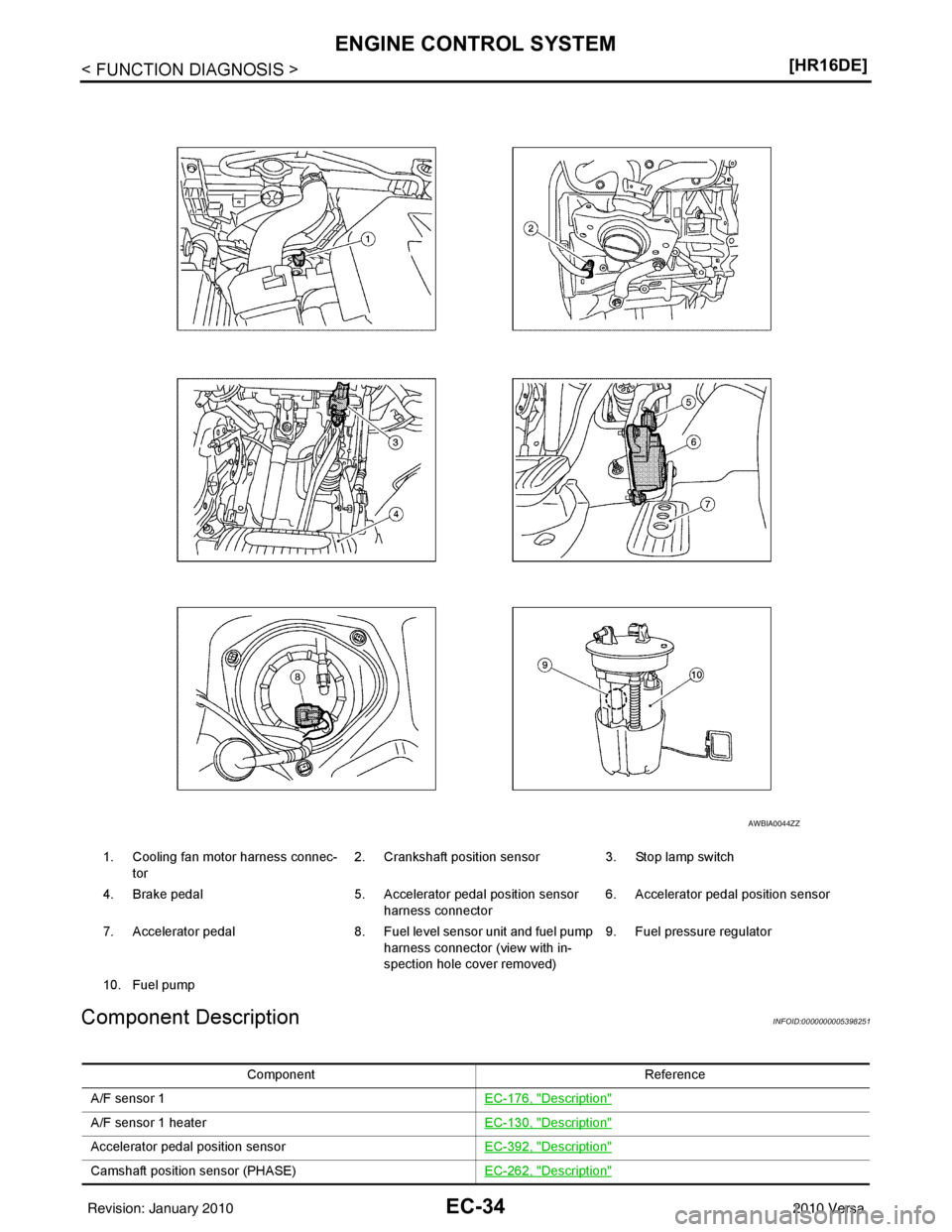
Component Description
INFOID:0000000005398251
1. Cooling fan motor harness connec- tor 2. Crankshaft position sensor
3. Stop lamp switch
4. Brake pedal 5. Accelerator pedal position sensor
harness connector 6. Accelerator pedal position sensor
7. Accelerator pedal 8. Fuel level sensor unit and fuel pump
harness connector (view with in-
spection hole cover removed) 9. Fuel pressure regulator
10. Fuel pump
AWBIA0044ZZ
Component Reference
A/F sensor 1 EC-176, "
Description"
A/F sensor 1 heaterEC-130, "Description"
Accelerator pedal position sensorEC-392, "Description"
Camshaft position sensor (PHASE)EC-262, "Description"
Revision: January 20102010 Versa
Page 1300 of 3745
ENGINE CONTROL SYSTEMEC-35
< FUNCTION DIAGNOSIS > [HR16DE]
C
D
E
F
G H
I
J
K L
M A
EC
NP
O
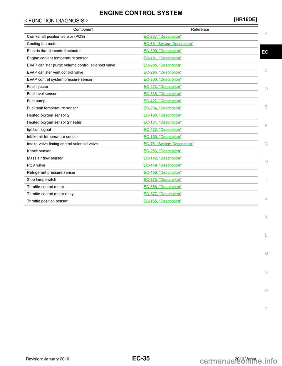
Crankshaft position sensor (POS)
EC-257, "Description"
Cooling fan motorEC-60, "System Description"
Electric throttle control actuatorEC-390, "Description"
Engine coolant temperature sensorEC-161, "Description"
EVAP canister purge volume control solenoid valveEC-285, "Description"
EVAP canister vent control valveEC-295, "Description"
EVAP control system pressure sensorEC-306, "Description"
Fuel injectorEC-423, "Description"
Fuel level sensorEC-336, "Description"
Fuel pumpEC-427, "Description"
Fuel tank temperature sensorEC-234, "Description"
Heated oxygen sensor 2EC-198, "Description"
Heated oxygen sensor 2 heaterEC-134, "Description"
Ignition signalEC-432, "Description"
Intake air temperature sensorEC-156, "Description"
Intake valve timing control solenoid valveEC-78, "System Description"
Knock sensorEC-253, "Description"
Mass air flow sensorEC-142, "Description"
PCV valveEC-449, "Description"
Refrigerant pressure sensorEC-450, "Description"
Stop lamp switchEC-373, "Description"
Throttle control motorEC-386, "Description"
Throttle control motor relayEC-377, "Description"
Throttle position sensorEC-165, "Description"
Component Reference
Revision: January 20102010 Versa
Page 1366 of 3745
ON BOARD DIAGNOSTIC (OBD) SYSTEMEC-101
< FUNCTION DIAGNOSIS > [HR16DE]
C
D
E
F
G H
I
J
K L
M A
EC
NP
O
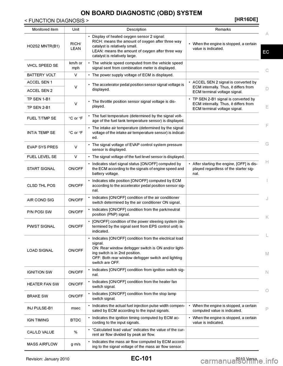
HO2S2 MNTR(B1)
RICH/
LEAN • Display of heated oxygen sensor 2 signal:
RICH: means the amount of oxygen after three way
catalyst is relatively small.
LEAN: means the amount of oxygen after three way
catalyst is relatively large. • When the engine is stopped, a certain
value is indicated.
VHCL SPEED SE km/h or
mph • The vehicle speed computed from the vehicle speed
signal sent from combination meter is displayed.
BATTERY VOLT V • The power supply voltage of ECM is displayed.
ACCEL SEN 1 V• The accelerator pedal position sensor signal voltage is
displayed. • ACCEL SEN 2 signal is converted by
ECM internally. Thus, it differs from
ECM terminal voltage signal.
ACCEL SEN 2
TP SEN 1-B1
V• The throttle position sensor signal voltage is dis-
played. • TP SEN 2-B1 signal is converted by
ECM internally. Thus, it differs from
ECM terminal voltage signal.
TP SEN 2-B1
FUEL T/TMP SE
°C or °F • The fuel temperature (determined by the signal volt-
age of the fuel tank temperature sensor) is displayed.
INT/A TEMP SE °C or °F • The intake air temperature (determined by the signal
voltage of the intake air temperature sensor) is indicat-
ed.
EVAP SYS PRES V • The signal voltage of EVAP control system pressure
sensor is displayed.
FUEL LEVEL SE V • The signal voltage of the fuel level sensor is displayed.
START SIGNAL ON/OFF • Indicates start signal status [ON/OFF] computed by
the ECM according to the signals of engine speed and
battery voltage. • After starting the engine, [OFF] is dis-
played regardless of the starter sig-
nal.
CLSD THL POS ON/OFF • Indicates idle position [ON/OFF] computed by ECM
according to the accelerator pedal position sensor sig-
nal.
AIR COND SIG ON/OFF • Indicates [ON/OFF] condition of the air conditioner
switch determined by the air conditioner ON signal.
P/N POSI SW ON/OFF • Indicates [ON/OFF] condit
ion from the park/neutral
position (PNP) signal.
PW/ST SIGNAL ON/OFF • [ON/OFF] condition of the power steering system (de-
termined by the signal sent from EPS control unit) is
indicated.
LOAD SIGNAL ON/OFF • Indicates [ON/OFF] condition from the electrical load
signal.
ON: Rear window defogger switch is ON and/or light-
ing switch is in 2nd position.
OFF: Both rear window defogger switch and lighting
switch are OFF.
IGNITION SW ON/OFF • Indicates [ON/OFF] condition from ignition switch sig-
nal.
HEATER FAN SW ON/OFF • Indicates [ON/OFF] condition from the heater fan
switch signal.
BRAKE SW ON/OFF• Indicates [ON/OFF] condition from the stop lamp
switch signal.
INJ PULSE-B1 msec • Indicates the actual fuel injection pulse width compen-
sated by ECM according to the input signals. • When the engine is stopped, a certain
computed value is indicated.
IGN TIMING BTDC• Indicates the ignition timing computed by ECM ac-
cording to the input signals. • When the engine is stopped, a certain
value is indicated.
CAL/LD VALUE %• “Calculated load value” indicates the value of the cur-
rent air flow divided by peak air flow.
MASS AIRFLOW g·m/s • Indicates the mass air flow computed by ECM accord-
ing to the signal voltage of the mass air flow sensor.
Monitored item Unit
DescriptionRemarks
Revision: January 20102010 Versa
Page 1367 of 3745
EC-102
< FUNCTION DIAGNOSIS >[HR16DE]
ON BOARD DIAGNOSTIC (OBD) SYSTEM
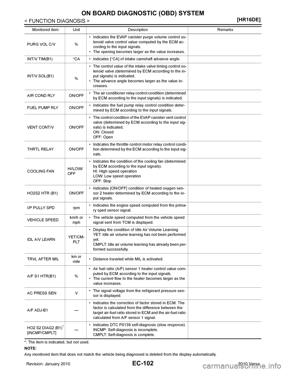
*: The item is indicated, but not used.
NOTE:
Any monitored item that does not match the vehicle being diagnosed is deleted from the display automatically.PURG VOL C/V %
• Indicates the EVAP canister purge volume control so-
lenoid valve control value computed by the ECM ac-
cording to the input signals.
• The opening becomes larger as the value increases.
INT/V TIM(B1) °CA • Indicates [ °CA] of intake camshaft advance angle.
INT/V SOL(B1) %• The control value of the intake valve timing control so-
lenoid valve (determined by ECM according to the in-
put signals) is indicated.
• The advance angle becomes larger as the value in- creases.
AIR COND RLY ON/OFF • The air conditioner relay control condition (determined
by ECM according to the input signals) is indicated.
FUEL PUMP RLY ON/OFF • Indicates the fuel pump relay control condition deter-
mined by ECM according to the input signals.
VENT CONT/V ON/OFF • The control condition of the EVAP canister vent control
valve (determined by ECM according to the input sig-
nals) is indicated.
ON: Closed
OFF: Open
THRTL RELAY ON/OFF • Indicates the throttle contro
l motor relay control condi-
tion determined by the ECM according to the input sig-
nals.
COOLING FAN HI/LOW/
OFF• Indicates the condition of the cooling fan (determined
by ECM according to the input signals).
HI: High speed operation
LOW: Low speed operation
OFF: Stop
HO2S2 HTR (B1) ON/OFF • Indicates [ON/OFF] condition of heated oxygen sen-
sor 2 heater determined by ECM according to the in-
put signals.
I/P PULLY SPD rpm • Indicates the engine speed computed from the prima-
ry sped sensor signal.
VEHICLE SPEED km/h or
mph • The vehicle speed computed from the vehicle speed
signal sent from TCM is displayed.
IDL A/V LEARN YET/CM-
PLT • Display the condition of Idle Air Volume Learning
YET: Idle air volume learning has not been performed
yet.
CMPLT: Idle air volume learning has already been per-
formed successfully.
TRVL AFTER MIL km or
mile • Distance traveled while MIL is activated.
A/F S1 HTR(B1) % • Air fuel ratio (A/F) sensor 1 heater control value com-
puted by ECM according to the input signals.
• The current flow to the heater becomes larger as the value increases.
AC PRESS SEN V • The signal voltage from the refrigerant pressure sen-
sor is displayed.
A/F ADJ-B1 —• Indicates the correction of factor stored in ECM. The
factor is calculated from the difference between the
target air-fuel ratio stored in ECM and the air-fuel ratio
calculated from A/F sensor 1 signal.
HO2 S2 DIAG2 (B1)
*
[INCMP/CMPLT] —• Indicates DTC P0139 self-diagnosis (slow responce)
INCMP: Self-diagnosis is incomplete.
CMPLT: Self-diagnosis is complete.
Monitored item Unit
DescriptionRemarks
Revision: January 20102010 Versa
Page 1395 of 3745
EC-130
< COMPONENT DIAGNOSIS >[HR16DE]
P0031, P0032 A/F SENSOR 1 HEATER
P0031, P0032 A/F SENSOR 1 HEATER
DescriptionINFOID:0000000005398303
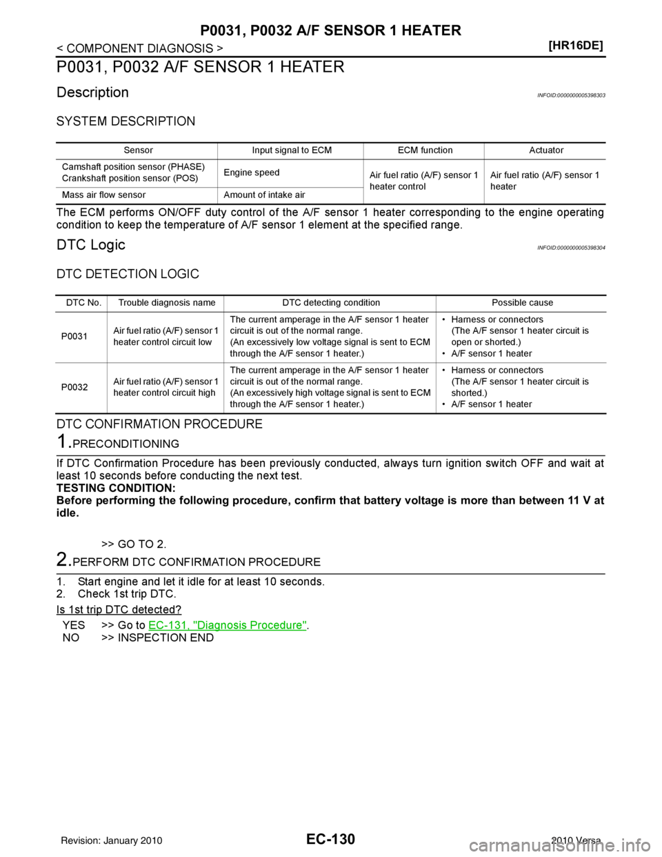
SYSTEM DESCRIPTION
The ECM performs ON/OFF duty control of the A/F
sensor 1 heater corresponding to the engine operating
condition to keep the temperature of A/F sensor 1 element at the specified range.
DTC LogicINFOID:0000000005398304
DTC DETECTION LOGIC
DTC CONFIRMATION PROCEDURE
1.PRECONDITIONING
If DTC Confirmation Procedure has been previously conducted, always turn ignition switch OFF and wait at
least 10 seconds before conducting the next test.
TESTING CONDITION:
Before performing the following procedure, confirm th at battery voltage is more than between 11 V at
idle.
>> GO TO 2.
2.PERFORM DTC CONFIRMATION PROCEDURE
1. Start engine and let it idle for at least 10 seconds.
2. Check 1st trip DTC.
Is 1st trip DTC detected?
YES >> Go to EC-131, "Diagnosis Procedure".
NO >> INSPECTION END
Sensor Input signal to ECM ECM functionActuator
Camshaft position sensor (PHASE)
Crankshaft position sensor (POS) Engine speed
Air fuel ratio (A/F) sensor 1
heater control Air fuel ratio (A/F) sensor 1
heater
Mass air flow sensor Amount of intake air
DTC No. Trouble diagnosis name DTC detecting conditionPossible cause
P0031 Air fuel ratio (A/F) sensor 1
heater control circuit low The current amperage in the A/F sensor 1 heater
circuit is out of the normal range.
(An excessively low voltage signal is sent to ECM
through the A/F sensor 1 heater.) • Harness or connectors
(The A/F sensor 1 heater circuit is
open or shorted.)
• A/F sensor 1 heater
P0032 Air fuel ratio (A/F) sensor 1
heater control circuit high The current amperage in the A/F sensor 1 heater
circuit is out of the normal range.
(An excessively high voltage signal is sent to ECM
through the A/F sensor 1 heater.) • Harness or connectors
(The A/F sensor 1 heater circuit is
shorted.)
• A/F sensor 1 heater
Revision: January 20102010 Versa