2010 NISSAN TIIDA air bleeding
[x] Cancel search: air bleedingPage 887 of 3745
REAR DRUM BRAKEBR-39
< SERVICE INFORMATION >
C
DE
G H
I
J
K L
M A
B
BR
N
O P
5. Connect the parking brake rear cable to the operating lever.
6. Install the shoe assembly. After assembly, be sure that each part is installed properly. CAUTION:
Do not damage the wheel cylinder piston boot.
7. Install the brake drum.
8. Depress brake pedal for several times (approximately 2 or 3 times).
9. Adjust clearance of brake shoe. Refer to PB-5, "
On-Vehicle Service".
10. Install rear wheel and tire. Refer to WT-7, "
Adjustment".
Removal and Installati on of Wheel CylinderINFOID:0000000005397005
REMOVAL
1. Drain the brake fluid. Refer to BR-9, "Drain and Refill".
2. Remove the rear brake shoe assembly. Refer to BR-36, "
Removal and Installation of Drum Brake Assem-
bly".
3. Remove the bleed valve.
4. Disconnect the brake tube from the wheel cylinder.
5. Remove the wheel cylinder bolts and then remove the wheel cylinder from the back plate.
INSTALLATION
Installation is in the reverse order of removal.
• Tighten bolts and bleed valve to the specified torque. Refer to BR-35, "
Component".
• Refill with new brake fluid and bleed the air. Refer to BR-9, "
Bleeding Brake System".
Disassembly and Assembly of Wheel CylinderINFOID:0000000005397006
DISASSEMBLY
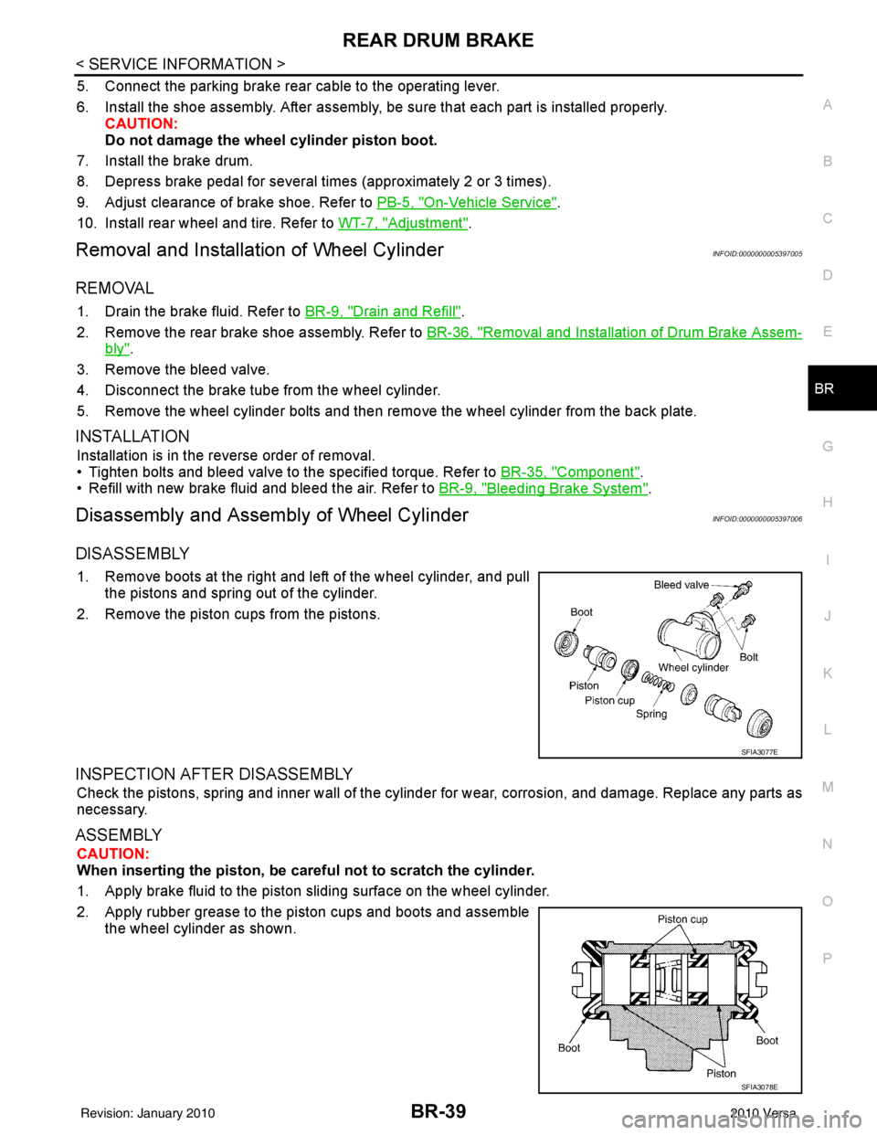
1. Remove boots at the right and left of the wheel cylinder, and pull
the pistons and spring out of the cylinder.
2. Remove the piston cups from the pistons.
INSPECTION AFTER DISASSEMBLY
Check the pistons, spring and inner wall of the cylinder for wear, corrosion, and damage. Replace any parts as
necessary.
ASSEMBLY
CAUTION:
When inserting the piston, be caref ul not to scratch the cylinder.
1. Apply brake fluid to the piston sliding surface on the wheel cylinder.
2. Apply rubber grease to the piston cups and boots and assemble the wheel cylinder as shown.
SFIA3077E
SFIA3078E
Revision: January 20102010 Versa
Page 927 of 3745
![NISSAN TIIDA 2010 Service Repair Manual ACTUATOR AND ELECTRIC UNIT (ASSEMBLY)BRC-37
< SERVICE INFORMATION > [ABS]
C
D
E
G H
I
J
K L
M A
B
BRC
N
O P
ACTUATOR AND ELECTRIC UNIT (ASSEMBLY)
Removal and InstallationINFOID:0000000005397053
CAUTIO](/manual-img/5/57397/w960_57397-926.png "NISSAN TIIDA 2010 Service Repair Manual ACTUATOR AND ELECTRIC UNIT (ASSEMBLY)BRC-37
< SERVICE INFORMATION > [ABS]
C
D
E
G H
I
J
K L
M A
B
BRC
N
O P
ACTUATOR AND ELECTRIC UNIT (ASSEMBLY)
Removal and InstallationINFOID:0000000005397053
CAUTIO")
ACTUATOR AND ELECTRIC UNIT (ASSEMBLY)BRC-37
< SERVICE INFORMATION > [ABS]
C
D
E
G H
I
J
K L
M A
B
BRC
N
O P
ACTUATOR AND ELECTRIC UNIT (ASSEMBLY)
Removal and InstallationINFOID:0000000005397053
CAUTION:
• Before servicing, disconnect battery negative terminal.
• To remove brake tube, use flare nut wrench to pr event flare nuts and brake tube from being dam-
aged. To install, use flare nut torque wrench, ti ghten flare nut to the specified torque. Refer to BR-11,
"Hydraulic Circuit".
• Do not apply excessive impact to ABS actuator and elect ric unit (control unit), such as dropping it.
• Do not remove and install actuator by holding harness.
• After work is completed, bleed the air from the brake hydraulic system. Refer to BR-9, "
Bleeding
Brake System".
REMOVAL
1. Disconnect the battery negative terminal.
2. Remove the cowl top. Refer to EI-22, "
Removal and Installation".
3. Disconnect ABS actuator and electric unit (control unit) connector.
4. Loosen brake tube flare nuts, then remove brake tubes from ABS actuator and electric unit (control unit).
5. Remove brake booster hose from engine. Refer to BR-23, "
Removal and Installation".
6. Remove ABS actuator and electric unit (control unit) bracket bolts.
7. Remove ABS actuator and electric unit (control unit).
1. To front right caliper 2. To rear left wheel cylinder 3. To rear right wheel cylinder
4. To front left caliper 5. From master cylinder primary side 6. From master cylinder secondary side
7. ABS actuator and electric unit (control unit) 8. Harness connector
Front
AWFIA0532GB
Revision: January 20102010 Versa
Page 979 of 3745
![NISSAN TIIDA 2010 Service Repair Manual ACTUATOR AND ELECTRIC UNIT (ASSEMBLY)BRC-89
< SERVICE INFORMATION > [VDC/TCS/ABS]
C
D
E
G H
I
J
K L
M A
B
BRC
N
O P
ACTUATOR AND ELECTRIC UNIT (ASSEMBLY)
Removal and InstallationINFOID:000000000561225](/manual-img/5/57397/w960_57397-978.png "NISSAN TIIDA 2010 Service Repair Manual ACTUATOR AND ELECTRIC UNIT (ASSEMBLY)BRC-89
< SERVICE INFORMATION > [VDC/TCS/ABS]
C
D
E
G H
I
J
K L
M A
B
BRC
N
O P
ACTUATOR AND ELECTRIC UNIT (ASSEMBLY)
Removal and InstallationINFOID:000000000561225")
ACTUATOR AND ELECTRIC UNIT (ASSEMBLY)BRC-89
< SERVICE INFORMATION > [VDC/TCS/ABS]
C
D
E
G H
I
J
K L
M A
B
BRC
N
O P
ACTUATOR AND ELECTRIC UNIT (ASSEMBLY)
Removal and InstallationINFOID:0000000005612259
CAUTION:
• Before servicing, disconnect battery negative terminal.
• To remove brake tube, use flare nut wrench to pr event flare nuts and brake tube from being dam-
aged. To install, use flare nut torque wrench, ti ghten flare nut to the specified torque. Refer to BR-11,
"Hydraulic Circuit".
• Do not apply excessive impact to ABS actuator and elect ric unit (control unit), such as dropping it.
• Do not remove and install actuator by holding harness.
• After work is completed, bleed the air from the brake hydraulic system. Refer to BR-9, "
Bleeding
Brake System".
REMOVAL
1. Disconnect the battery negative terminal.
2. Remove the cowl top. Refer to EI-22, "
Removal and Installation".
3. Disconnect ABS actuator and electric unit (control unit) connector.
4. Loosen brake tube flare nuts, then remove brake tubes from ABS actuator and electric unit (control unit).
5. Remove brake booster hose from engine. Refer to BR-23, "
Removal and Installation".
6. Remove ABS actuator and electric unit (control unit) bracket bolts.
7. Remove ABS actuator and electric unit (control unit).
1. To front right caliper 2. To rear left wheel cylinder 3. To rear right wheel cylinder
4. To front left caliper 5. From master cylinder primary side 6. From master cylinder secondary side
7. ABS actuator and electric unit (control unit) 8. Harness connector
Front
AWFIA0532GB
Revision: January 20102010 Versa
Page 2551 of 3745
![NISSAN TIIDA 2010 Service Repair Manual EM-192
< SERVICE INFORMATION >[MR18DE]
ENGINE ASSEMBLY
• Use either 2-pole lift type or separate type lift as
best you can. If board-on type is used for unavoid-
able reasons, support at the rear a](/manual-img/5/57397/w960_57397-2550.png "NISSAN TIIDA 2010 Service Repair Manual EM-192
< SERVICE INFORMATION >[MR18DE]
ENGINE ASSEMBLY
• Use either 2-pole lift type or separate type lift as
best you can. If board-on type is used for unavoid-
able reasons, support at the rear a")
EM-192
< SERVICE INFORMATION >[MR18DE]
ENGINE ASSEMBLY
• Use either 2-pole lift type or separate type lift as
best you can. If board-on type is used for unavoid-
able reasons, support at the rear axle jacking point with a transmission jack or similar tool before
starting work, in preparation for the backward shift of center of gravity.
• For supporting points for lifting and jacking point at rear axle, refer to GI-38, "
Garage Jack and
Safety Stand and 2-Pole Lift".
REMOVAL
Remove the engine and the transaxle assembly from t he vehicle downward. Separate the engine and the tran-
saxle.
1. Remove engine under cover. Refer to EI-15, "
Removal and Installation".
2. Drain engine coolant from radiator. Refer to CO-36, "
Changing Engine Coolant".
CAUTION:
• Perform this step when the engine is cold.
• Do not spill engine coolant on drive belt.
3. Drain clutch fluid (M/T models). Refer to CL-9, "
Air Bleeding Procedure".
4. Drain M/T oil (M/T models). Refer to MT-54, "
Changing M/T Oil".
5. Remove front fender protector (RH and LH). Refer to EI-24
.
6. Remove exhaust front tube. Refer to EX-11
.
7. Remove drive shafts (LH and RH) from steering knuckle. Refer to FA X - 9
.
8. Remove transaxle joint bolts which pierce at oil pan (upper) lower rear side. Refer to AT-233
(A/T models),
CVT-173, "
Removal and Installation" (CVT models) or MT-61, "Removal and Installation" (M/T models).
9. Remove rear torque rod (1). NOTE:
A/T model shown CVT and M/T models similar.
10. Remove hood assembly. Refer to BL-13
.
11. Remove cowl top cover and cowl top extension assembly. Refer to EI-22
.
12. Release fuel pressure. Refer to EC-582, "
Fuel Pressure Check".
13. Remove battery and battery tray. Refer to SC-5
.
14. Remove drive belt; Refer to EM-132, "
Component".
15. Remove engine room cover.
16. Remove air duct and air cleaner case assembly. Refer to EM-135
.
17. Remove cooling fan assembly. Refer to CO-43, "
Removal and Installation".
18. Remove radiator hose (upper and lower). Refer to CO-40
.
19. Disconnect A/T, CVT fluid cooler hoses (A/T or CVT models). Refer to CO-40
.
20. Disconnect all connections of engine harness around the engine mounting insulator (LH), and then tem- porarily secure the engine harness into the engine side.
CAUTION:
Protect connectors using a resin bag to protect against foreign materials during the operation.
21. Disconnect fuel feed hose at engine side. Refer to EM-152, "
Component".
22. Disconnect heater hoses, and install plugs in them to prevent engine coolant from draining. Refer to CO-
48, "Component".
23. Disconnect control cable from transaxle. Refer to CVT-173, "
Removal and Installation" (CVT models), AT-
213 (A/T models) or MT-61, "Removal and Installation" (M/T models).
24. Remove ground cable at transaxle side.
25. Remove ground cable between front cover and vehicle.
26. Remove generator. Refer to SC-21
.
LBIA0460E
Revision: January 20102010 Versa
Page 3137 of 3745

MA-2
OIL FILTER : Removal and Installation ..................33
SPARK PLUG ........................................................ ...34
SPARK PLUG : Component ...................................34
SPARK PLUG : Removal and Installation ..............35
EVAP VAPOR LINES ............................................. ...36
EVAP VAPOR LINES : Checking EVAP Vapor
Line .........................................................................
36
CHASSIS AND BODY MAINTENANCE ............37
IN-CABIN MICROFILTER ...................................... ...37
IN-CABIN MICROFILTER : Removal and Installa-
tion ..........................................................................
37
EXHAUST SYSTEM ............................................... ...37
EXHAUST SYSTEM : Checking Exhaust System
HR16DE .............................................................. ...
37
EXHAUST SYSTEM : Checking Exhaust System
MR18DE .............................................................. ...
38
CVT FLUID ............................................................. ...38
CVT FLUID : Checking CVT Fluid ..........................38
CVT FLUID : Changing CVT Fluid ..........................39
CLUTCH FLUID ..................................................... ...39
CLUTCH FLUID : Air Bleeding Procedure ..............39
M/T OIL ................................................................... ...41
M/T OIL : Draining (RS5F91R) ...............................41
M/T OIL : Refilling (RS5F91R) ................................41
M/T OIL : Inspection (RS5F91R) ............................41
M/T OIL : Changing M/T Oil (RS6F94R) .................42
M/T OIL : Checking M/T Oil (RS6FF94R) ...............42
A/T FLUID .............................................................. ...42
A/T FLUID : Checking A/T Fluid .............................43
A/T FLUID : Changing A/T Fluid .............................43
WHEELS ................................................................. ...44
WHEELS : Balancing Wheels .................................44
WHEELS : Rotation ................................................44
BRAKE FLUID LEVEL AND LEAKS ..................... ...44
BRAKE FLUID LEVEL AND LEAKS : On Board In-
spection ...................................................................
44
BRAKE FLUID LEVEL AND LEAKS : Drain and
Refill ........................................................................
44
BRAKE LINES AND CABLES ............................... ...45
BRAKE LINES AND CABLES : Checking Brake
Line and Cables ................................................... ...
45
DISC BRAKE .......................................................... ...45
DISC BRAKE : On Board Inspection ......................45
DRUM BRAKE ....................................................... ...45
DRUM BRAKE : Inspection .....................................46
AXLE AND SUSPENSION PARTS ........................ ...46
AXLE AND SUSPENSION PARTS : Axle and
Suspension Parts ................................................. ...
47
DRIVE SHAFT ........................................................ ...47
DRIVE SHAFT : Drive Shaft ...................................47
LOCKS, HINGES AND HOOD LATCH .................. ...47
LOCKS, HINGES AND HOOD LATCH : Lubricat-
ing Locks, Hinges and Hood Latch .........................
48
SEAT BELT, BUCKLES, RETRACTORS, AN-
CHORS AND ADJUSTERS ................................... ...
48
SEAT BELT, BUCKLES, RETRACTORS, AN-
CHORS AND ADJUSTERS : Checking Seat
Belts, Buckles, Retractors, Anchors and Adjusters
...
48
Revision: January 20102010 Versa
Page 3174 of 3745
CHASSIS AND BODY MAINTENANCEMA-39
< SERVICE INFORMATION >
C
DE
F
G H
I
J
K
M A
B
MA
N
O P
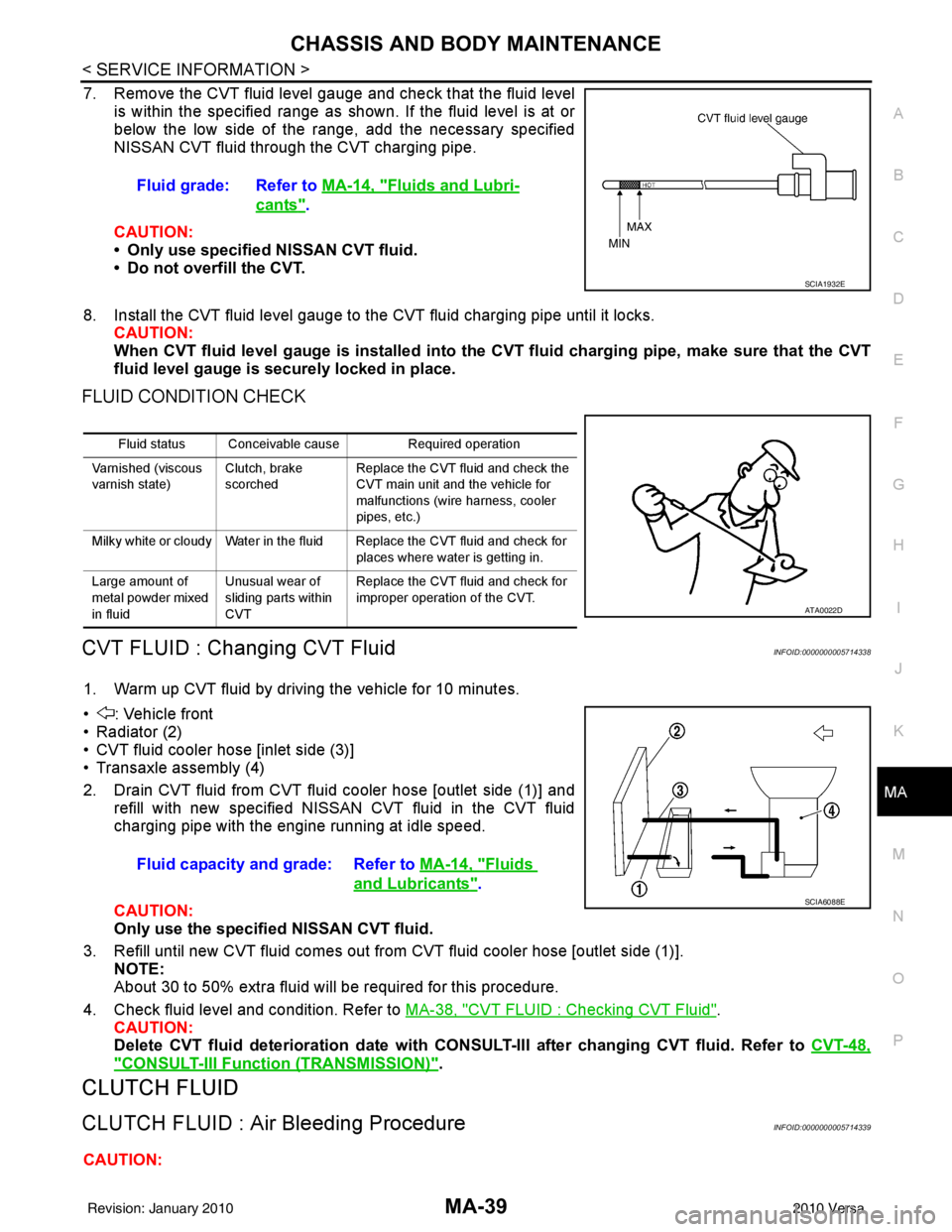
7. Remove the CVT fluid level gauge and check that the fluid level is within the specified range as shown. If the fluid level is at or
below the low side of the range, add the necessary specified
NISSAN CVT fluid through the CVT charging pipe.
CAUTION:
• Only use specified NISSAN CVT fluid.
• Do not overfill the CVT.
8. Install the CVT fluid level gauge to the CVT fluid charging pipe until it locks. CAUTION:
When CVT fluid level gauge is installed into the CVT fluid charging pipe, make sure that the CVT
fluid level gauge is securely locked in place.
FLUID CONDITION CHECK
CVT FLUID : Changing CVT FluidINFOID:0000000005714338
1. Warm up CVT fluid by driving the vehicle for 10 minutes.
• : Vehicle front
• Radiator (2)
• CVT fluid cooler hose [inlet side (3)]
• Transaxle assembly (4)
2. Drain CVT fluid from CVT fluid cooler hose [outlet side (1)] and refill with new specified NISSAN CVT fluid in the CVT fluid
charging pipe with the engine running at idle speed.
CAUTION:
Only use the specifi ed NISSAN CVT fluid.
3. Refill until new CVT fluid comes out from CVT fluid cooler hose [outlet side (1)]. NOTE:
About 30 to 50% extra fluid will be required for this procedure.
4. Check fluid level and condition. Refer to MA-38, "
CVT FLUID : Checking CVT Fluid".
CAUTION:
Delete CVT fluid deterioration date with CONSULT-III after changing CVT fluid. Refer to CVT-48,
"CONSULT-III Function (TRANSMISSION)".
CLUTCH FLUID
CLUTCH FLUID : Air Bleeding ProcedureINFOID:0000000005714339
CAUTION:Fluid grade: Refer to
MA-14, "
Fluids and Lubri-
cants".
SCIA1932E
Fluid status Conceivable cause Required operation
Varnished (viscous
varnish state) Clutch, brake
scorchedReplace the CVT fluid and check the
CVT main unit and the vehicle for
malfunctions (wire harness, cooler
pipes, etc.)
Milky white or cloudy Water in the fluid Replace the CVT fluid and check for places where water is getting in.
Large amount of
metal powder mixed
in fluid Unusual wear of
sliding parts within
CVTReplace the CVT fluid and check for
improper operation of the CVT.
ATA0022D
Fluid capacity and grade: Refer to
MA-14, "Fluids
and Lubricants".SCIA6088E
Revision: January 20102010 Versa
Page 3175 of 3745
MA-40
< SERVICE INFORMATION >
CHASSIS AND BODY MAINTENANCE
Do not spill clutch fluid onto painted surfaces. If it spills, wipe up immediately and wash the affected
area with water.
NOTE:
• Do not use a vacuum assist or any other type of power bleeder on this system. Use of a vacuum assist or power bleeder will not purge all the air from the system.
• Carefully monitor fluid level in reservoir tank during bleeding operation.
1. Fill master cylinder reservoir tank with new clutch fluid.
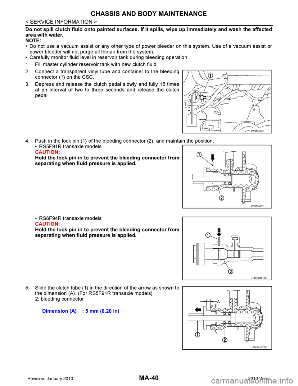
2. Connect a transparent vinyl tube and container to the bleeding connector (1) on the CSC.
3. Depress and release the clutch pedal slowly and fully 15 times at an interval of two to three seconds and release the clutch
pedal.
4. Push in the lock pin (1) of the bleeding connector (2), and maintain the position. • RS5F91R transaxle models
CAUTION:
Hold the lock pin in to preven t the bleeding connector from
separating when fluid pressure is applied.
• RS6F94R transaxle models
CAUTION:
Hold the lock pin in to preven t the bleeding connector from
separating when fluid pressure is applied.
5. Slide the clutch tube (1) in the direction of the arrow as shown to the dimension (A). (For RS5F91R transaxle models)
2: bleeding connector
PCIB1494E
PCIB1495E
JPDIB0041ZZ
Dimension (A) : 5 mm (0.20 in)
JPDIB0147ZZ
Revision: January 20102010 Versa
Page 3176 of 3745
CHASSIS AND BODY MAINTENANCEMA-41
< SERVICE INFORMATION >
C
DE
F
G H
I
J
K
M A
B
MA
N
O P
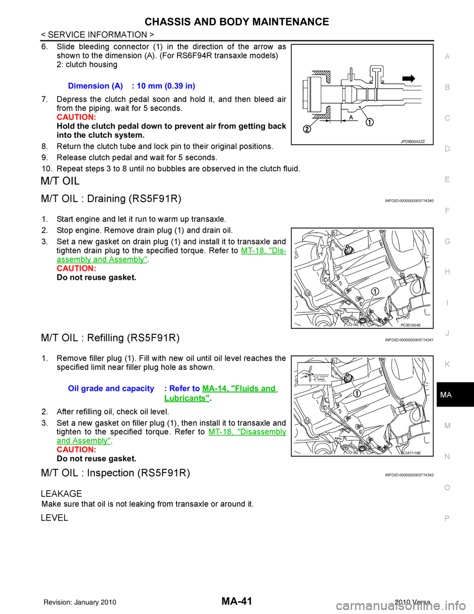
6. Slide bleeding connector (1) in the direction of the arrow as shown to the dimension (A). (For RS6F94R transaxle models)
2: clutch housing
7. Depress the clutch pedal soon and hold it, and then bleed air from the piping. wait for 5 seconds.
CAUTION:
Hold the clutch pedal down to prevent air from getting back
into the clutch system.
8. Return the clutch tube and lock pin to their original positions.
9. Release clutch pedal and wait for 5 seconds.
10. Repeat steps 3 to 8 until no bubbles are observed in the clutch fluid.
M/T OIL
M/T OIL : Draining (RS5F91R)INFOID:0000000005714340
1. Start engine and let it run to warm up transaxle.
2. Stop engine. Remove drain plug (1) and drain oil.
3. Set a new gasket on drain plug (1) and install it to transaxle and tighten drain plug to the specified torque. Refer to MT-18, "
Dis-
assembly and Assembly".
CAUTION:
Do not reuse gasket.
M/T OIL : Refilling (RS5F91R)INFOID:0000000005714341
1. Remove filler plug (1). Fill with new oil until oil level reaches the specified limit near filler plug hole as shown.
2. After refilling oil, check oil level.
3. Set a new gasket on filler plug (1), then install it to transaxle and tighten to the specified torque. Refer to MT-18, "
Disassembly
and Assembly".
CAUTION:
Do not reuse gasket.
M/T OIL : Inspection (RS5F91R)INFOID:0000000005714342
LEAKAGE
Make sure that oil is not leaking from transaxle or around it.
LEVEL
Dimension (A) : 10 mm (0.39 in)
JPDIB0042ZZ
PCIB1504E
Oil grade and capacity : Refer to MA-14, "Fluids and
Lubricants".
SCIA7119E
Revision: January 20102010 Versa