Page 3483 of 3745
WHEEL HUBRAX-7
< SERVICE INFORMATION >
CEF
G H
I
J
K L
M A
B
RAX
N
O P
Do not pull on wheel sensor harness.
3. Remove the drum brake assembly. Refer to BR-36, "
Removal and Installation of Drum Brake Assembly".
4. Remove wheel hub and bearing assembly bolts, and then remove wheel hub and bearing assembly from vehicle support back plate assembly.
INSPECTION AFTER REMOVAL
Check for any deformity, cracks, or other damage on the wheel hub assembly, replace if necessary.
CAUTION:
The wheel hub assembly does not requ ire maintenance. If any of the following symptoms are noted,
replace the wheel hub assembly.
• Growling noise is emitted from the wheel hub bearing during operation.
• Wheel hub bearing drags or turns roughly.
INSTALLATION
Installation is in the reverse order of removal.
Revision: January 20102010 Versa
Page 3526 of 3745
RSU-12
< SERVICE INFORMATION >
REAR SUSPENSION BEAM
REAR SUSPENSION BEAM
Removal and InstallationINFOID:0000000005397082
REMOVAL
1. Remove wheel and tire using power tool.
2. Separate parking brake rear cable from rear drum brake and rear suspension beam. Refer to PB-5, "
On-
Vehicle Service".
3. Remove wheel sensor and wheel sensor harness from wheel hub and bearing assembly and rear suspen-
sion beam. Refer to BRC-34, "
Removal and Installation".
4. Remove lock plate and separate brake tube from brake hose. Refer to BR-12, "
Rear Brake Tube and Hose".
5. Remove wheel hub and bearing assembly and back plate. Refer to RAX-6, "
On-Vehicle Inspection and Service".
6. Set jack under rear suspension beam.
7. Remove coil spring (left/right). Refer to RSU-11, "
Removal and
Installation".
8. Remove bolts between body and rear suspension beam bracket. Refer to RSU-8, "
Component".
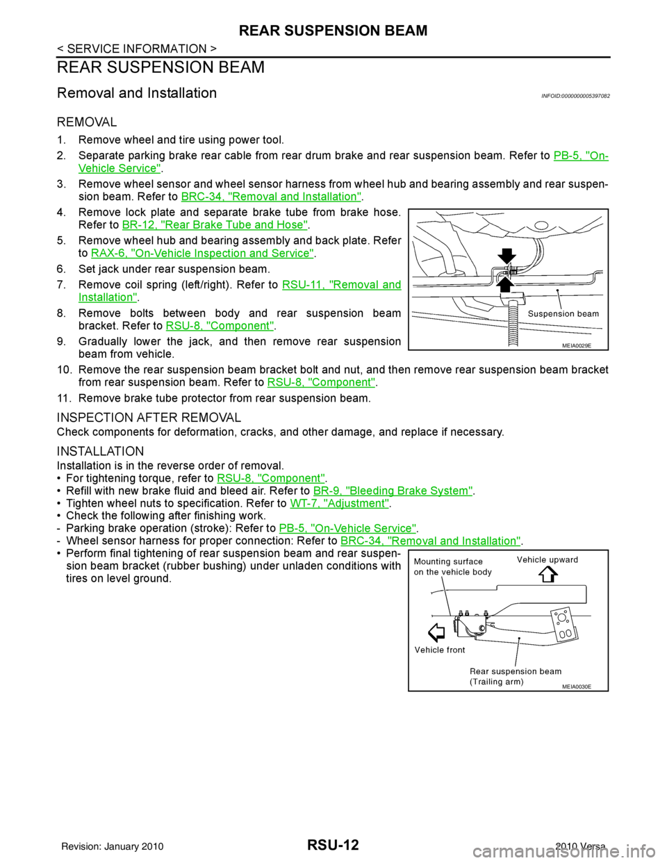
9. Gradually lower the jack, and then remove rear suspension beam from vehicle.
10. Remove the rear suspension beam bracket bolt and nut, and then remove rear suspension beam bracket
from rear suspension beam. Refer to RSU-8, "
Component".
11. Remove brake tube protector from rear suspension beam.
INSPECTION AFTER REMOVAL
Check components for deformation, cracks, and other damage, and replace if necessary.
INSTALLATION
Installation is in the reverse order of removal.
• For tightening torque, refer to RSU-8, "
Component".
• Refill with new brake fluid and bleed air. Refer to BR-9, "
Bleeding Brake System".
• Tighten wheel nuts to specification. Refer to WT-7, "
Adjustment".
• Check the following after finishing work.
- Parking brake operation (stroke): Refer to PB-5, "
On-Vehicle Service".
- Wheel sensor harness for proper connection: Refer to BRC-34, "
Removal and Installation".
• Perform final tightening of rear suspension beam and rear suspen-
sion beam bracket (rubber bushing) under unladen conditions with
tires on level ground.
MEIA0029E
MEIA0030E
Revision: January 20102010 Versa
Page 3547 of 3745
SC-8
< SERVICE INFORMATION >
BATTERY
CAUTION:
When disconnecting, disconnect the battery negative terminal first.
2. Remove battery hold-down wedge bolt (A) and remove battery hold-down wedge bracket (3).
3. Remove battery cover.
4. Remove battery.
INSTALLATION (All except MR18DE with CVT)
Installation is in the reverse order of removal.
CAUTION:
When connecting, connect the battery positive terminal first.
Reset electronic systems as necessary. Refer to SC-8, "
Required Procedure After Battery Disconnection".
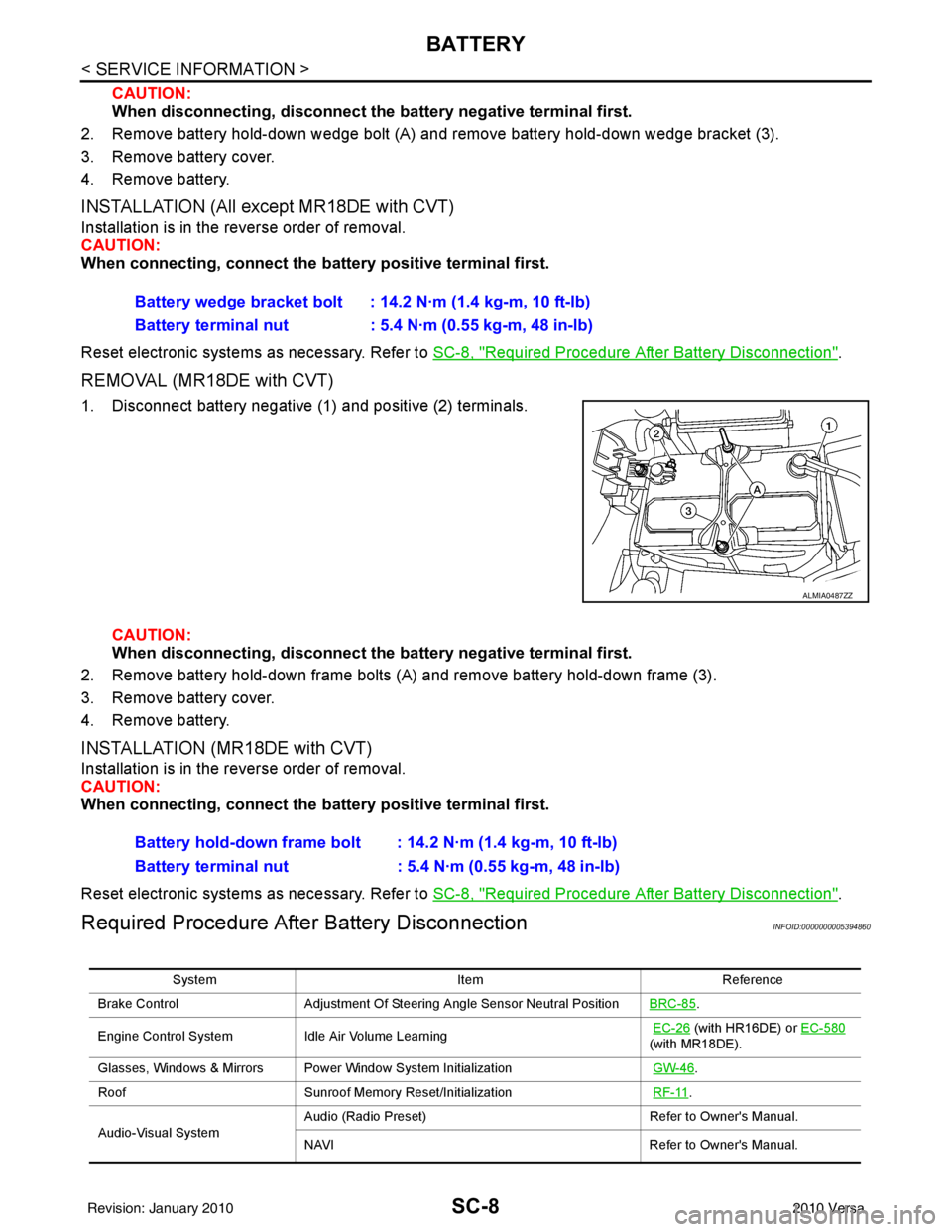
REMOVAL (MR18DE with CVT)
1. Disconnect battery negative (1) and positive (2) terminals.
CAUTION:
When disconnecting, disconnect th e battery negative terminal first.
2. Remove battery hold-down frame bolts (A) and remove battery hold-down frame (3).
3. Remove battery cover.
4. Remove battery.
INSTALLATION (MR18DE with CVT)
Installation is in the reverse order of removal.
CAUTION:
When connecting, connect the battery positive terminal first.
Reset electronic systems as necessary. Refer to SC-8, "
Required Procedure After Battery Disconnection".
Required Procedure After Battery DisconnectionINFOID:0000000005394860
Battery wedge bracket bolt : 14.2 N·m (1.4 kg-m, 10 ft-lb)
Battery terminal nut : 5.4 N·m (0.55 kg-m, 48 in-lb)
ALMIA0487ZZ
Battery hold-down frame bolt : 14.2 N·m (1.4 kg-m, 10 ft-lb)
Battery terminal nut : 5.4 N·m (0.55 kg-m, 48 in-lb)
System ItemReference
Brake Control Adjustment Of Steering Angle Sensor Neutral Position BRC-85
.
Engine Control System Idle Air Volume Learning
EC-26
(with HR16DE) or EC-580
(with MR18DE).
Glasses, Windows & Mirrors Power Window System Initialization GW-46
.
Roof Sunroof Memory Reset/Initialization RF-11
.
Audio-Visual System Audio (Radio Preset)
Refer to Owner's Manual.
NAVI Refer to Owner's Manual.
Revision: January 20102010 Versa