2010 NISSAN QASHQAI steering
[x] Cancel search: steeringPage 62 of 297
Downloaded from www.Manualslib.com manuals search engine For more information, see “Seat belts” in the
“1. Safety — seats, seat belts and supplemental
restraint system” section
j4 Ignition knob warning (Intelligent Key
models)
The warning appears when the ignition knob is left
in the Acc or “OFF” position instead of completely
being turned to the LOCK position.
If this warning appears, turn the ignition knob to the
LOCK position.
When the ignition knob is in the ON position, a
buzzer will sound twice and the ignition knob warn-
ing shows when the ignition knob is turned to the
Acc or “OFF” position. This is to warn the driver that
the ignition knob is not in the LOCK position.
MT models:
Depress the ignition PUSH release button and turn
the ignition knob to the LOCK position.
AT or CVT models:
Make sure the gear selector lever is in the P (Park)
position and then turn the ignition switch to the
LOCK position.
See “Ignition knob (where fitted)” in the “5. Starting
and driving” section for further details.
CAUTION
The steering wheel can only be locked when
the ignition knob is in the LOCK position. Make
sure the ignition knob is in the LOCK position
before leaving the vehicle.
The emergency key can only be removed at
the LOCK position. Make sure the ignition
knob is in the LOCK position before removing
the emergency key.
See “Steering lock” in the “5. Starting and driving”
section for further details.
j5 Steering wheel lock warning
The warning appears when the ignition knob is
pressed, but not turned to the Acc or “OFF” posi-
tion within a short period. Move the steering wheel
to release the lock and turn the ignition knob to Acc
or ON. The warning will turn off in approximately 5
seconds.
See “Steering lock” in the “5. Starting and driving”
section for further details.
j6 Brake/Clutch warning (where fitted)
When starting your vehicle, it is necessary to oper-
ate the brake (CVT and AT models) or clutch pedal
(MT models).
For more information, see “Starting the engine” in
the “5. Starting and driving” section.
j7 Handbrake reminder
The reminder will come on if the handbrake is on
whilst the vehicle is being driven.
A buzzer will also sound.
j8 Intelligent Key detection warning
If the Intelligent Key is taken outside of the vehicle
ID recognition zone while the ignition knob is in the
Acc or ON position, the Intelligent Key detection
warning will be displayed and a buzzer will sound.
The Intelligent Key detection warning disappears
when the Intelligent Key is placed back in the pas-
senger compartment.
The message also appears when you try to start the
vehicle if the Intelligent Key is not detected within
the vehicle.
For more information, see “Integrated keyfob/re-
mote control system” in the “3. Pre-driving checks
and adjustments” section.
j9 Intelligent Key low battery warning
The Intelligent Key low battery warning may show if
a low battery voltage is detected when the ignition
knob is turned from “OFF” to the ON position.
For more information, see “Integrated keyfob/Intel-
ligent Key battery replacement” in the “8. Mainte-
nance and do-it-yourself” section.
j10Intelligent Key system fault warning
CAUTION
If the Intelligent Key system fault warning comes
on, it may indicate a system malfunction. We rec-
ommend that you contact a NISSAN dealer or
qualified workshop for repair.
Instruments and controls2-13
Page 63 of 297

Downloaded from www.Manualslib.com manuals search engine For more information, see “Integrated keyfob/re-
mote control system” in the “3. Pre-driving checks
and adjustments” section.
j11Intelligent Key convenience mode alert
The Intelligent Key convenience mode alert shows
to confirm that convenience mode has been acti-
vated. See “Switching from Convenience mode to
Anti-hijack mode” in the “3. Pre-driving checks and
adjustments” section.
j12Intelligent Key anti–hijack alert
The Intelligent Key anti–hijack alert shows to con-
firm that anti-hijack mode has been activated. See
“Switching from Convenience mode to Anti-hijack
mode” in the “3. Pre-driving checks and
adjustments” section.
j13Engine oil level information
When turning the ignition to the ON position, the oil
message indicates the oil level.
The [Oil level OK] message indicates the oil level is
sufficient for driving. Push the
switch or the
steering wheel switchji (where fitted) when the
[Oil level OK] message shows to see a more de-
tailed oil level. (See Oil level
j14 )
NOTE
The [Oil level OK] message indication is dis-
played after the ignition switch has been turned
to the ON position and other warnings have been
shown. CAUTION
The engine oil level check is not designed to indi-
cate a low oil level. Use the dipstick to check the
oil level.
See “Engine oil” in the “8. Maintenance and
do-it-yourself” section.
j14Engine oil level
This display provides a visual representation of the
engine oil level.
j15Engine oil level low
If the oil level is not sufficient for driving, the [Oil
level low] message appears. Oil needs to be added
before driving.
CAUTION
The engine oil level should be checked regularly.
Operating with an insufficient amount of oil can
damage the engine and such damage is not cov-
ered by the warranty.
Park the vehicle at a safe location as soon as pos-
sible and fill the engine with the recommended en-
gine oil.
For checking the engine oil level and adding oil, see
“Engine oil” in the “8. Maintenance and
do-it-yourself” section.
j16Engine oil sensor warning
Please visit your local NISSAN dealer or qualified
workshop if this warning appears.
j17Diesel Particulate Filter warning
(where fitted)
See “Diesel Particulate Filter (DPF) (where fitted)”
in the “5. Starting and driving” section for further
details.
j18Setting menu operation alert
The alert shows when you try to operate the setting
menu while driving. The setting menu can only be
entered if the vehicle is stationary.
j19Maintenance due alert (where fitted)
This alert shows that maintenance is due. The mes-
sage is shown until the steering wheel switchji
(where fitted) is pressed. When the maintenance
due alert reaches 0 km (miles), the
symbol
flashes next to the odometer value.
CAUTION
The engine oil must be changed before the main-
tenance due alert is shown.
– Failure to do so risks causing damage to the engine.
– Continued driving after maintenance due alert reaches 0 km (miles) may result in reduced
engine performance. The engine malfunction
indicator light (orange) will illuminate.
– The DPF (where fitted) may also become satu- rated because regeneration is restricted once
the distance equals 0 km (miles)
Always visit a NISSAN dealer or qualified work-
shop to perform the maintenance and the reset.
2-14Instruments and controls
Page 64 of 297
![NISSAN QASHQAI 2010 Owners Manual Downloaded from www.Manualslib.com manuals search engine However reset is possible (only after the oil was
changed) using the [Service] menu item in the
[Settings] menu. See “[Maintenance]” later NISSAN QASHQAI 2010 Owners Manual Downloaded from www.Manualslib.com manuals search engine However reset is possible (only after the oil was
changed) using the [Service] menu item in the
[Settings] menu. See “[Maintenance]” later](/manual-img/5/56766/w960_56766-63.png)
Downloaded from www.Manualslib.com manuals search engine However reset is possible (only after the oil was
changed) using the [Service] menu item in the
[Settings] menu. See “[Maintenance]” later in this
section
Have the vehicle inspected by a NISSAN dealer
or qualified workshop if these conditions occur.
j20Distance to maintenance alert
(where fitted)
This alert reminds when maintenance is due in the
shown distance. The alert is shown for 10 seconds
at ignition ON, when the distance to the next main-
tenance interval is below 5000 km (3100 Miles).
The message is shown until the steering wheel
switch
ji (where fitted) is pressed.
NOTE
Visit a NISSAN dealer or qualified workshop
before the maintenance due alertj19reaches
0 km (miles) to perform maintenance (oil
change).
The maintenance interval will reduce faster
with certain types of driving, especially at low
speeds in urban conditions.
j21Tyre change alert
You can set a distance for changing tyres. See
“[Maintenance]” later in this section
j22Maintenance alert
You can set a distance for a non specific mainte-
nance item. See “[Maintenance]” later in this sec-
tion
j23Low temperature warning
If, during driving, the temperature falls below 4ºC
this alert will appear to indicate low outside air tem-
perature. You can switch the low temperature warn-
ing [On] or [Off]. See “[Units]” later in this section
CAUTION
Even if the alert is not on, there is no guarantee
that the road is free of hazards caused by in-
clement weather.
NOTE
The outside air temperature sensor is located at
the front of the vehicle. At low speeds the sensor
can be affected by engine heat, heat reflected
from the road surface and exhaust from other
vehicles, these influences can cause the display
to be inaccurate. To compensate, the outside air
temperature display is designed to react slowly
to increasing temperatures, but quickly to falling
temperatures.
j24Low fuel warning
This warning appears when the fuel level in the tank
is getting low. Refuel as soon as it is convenient,
preferably before the fuel gauge reaches the empty
position. For more information, see “Fuel gauge”
earlier in this section.
j25Driver alert
This warning appears when the previously set time
for a break is reached. You can set the time for up
to 6 hours in the setting menu. (See “Settings menu”
later in this section.)
Stop/Start System (where fitted)
For more information, see “Stop/Start System
(where fitted)” in the “5. Starting and driving” sec-
tion
j26Engine stop:
If the engine stops when the Stop/Start System is
activated, the message is shown.
j27Auto start deactivation:
If the engine stops when the Stop/Start System is
activated, and will not start automatically, the mes-
sage is shown.
j28System fault:
If the Stop/Start System is activated, but does not
operate correctly, the message is shown. Visit a
NISSAN dealer or qualified workshop.
Activating or deactivating using the Stop/Start
System OFF switch:
Using the Stop/Start System OFF switch activates
or deactivates the Stop/Start System. This is shown
in the vehicle information display:
j29 :The Stop/Start System OFF switch is
pushed to the “ON” position.
j30 :The Stop/Start System OFF switch is pushed to
the “OFF” position.
Instruments and controls2-15
Page 65 of 297
Downloaded from www.Manualslib.com manuals search engine ODOMETER/TWIN TRIP ODOMETER
The odometer and twin trip odometer are displayed
when the ignition switch is in the ON position.
Odometer
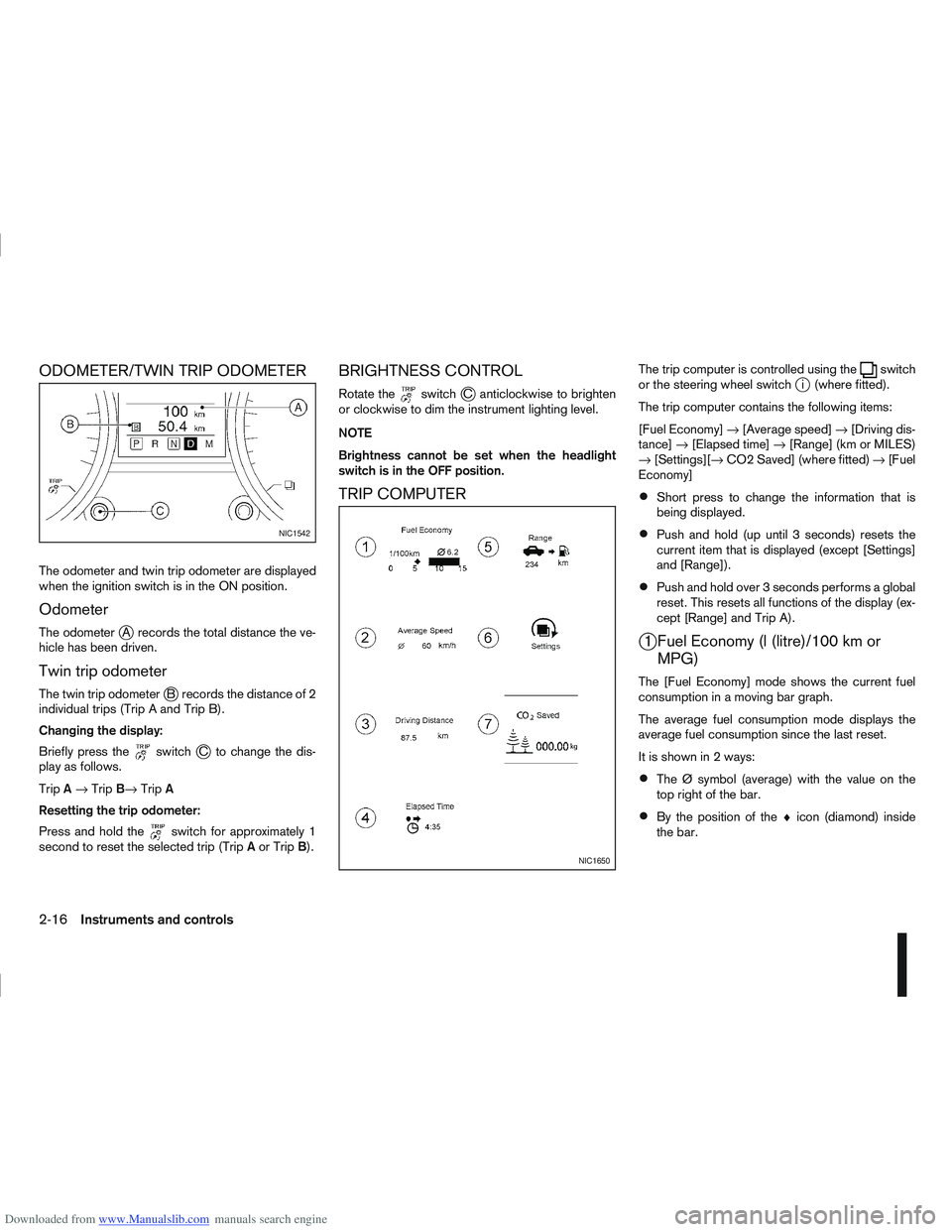
The odometerjA records the total distance the ve-
hicle has been driven.
Twin trip odometer
The twin trip odometerjB records the distance of 2
individual trips (Trip A and Trip B).
Changing the display:
Briefly press the
switchjC to change the dis-
play as follows.
Trip A→ Trip B→ TripA
Resetting the trip odometer:
Press and hold the
switch for approximately 1
second to reset the selected trip (Trip Aor Trip B).
BRIGHTNESS CONTROL
Rotate theswitchjC anticlockwise to brighten
or clockwise to dim the instrument lighting level.
NOTE
Brightness cannot be set when the headlight
switch is in the OFF position.
TRIP COMPUTER
The trip computer is controlled using theswitch
or the steering wheel switchji (where fitted).
The trip computer contains the following items:
[Fuel Economy] →[Average speed] →[Driving dis-
tance] →[Elapsed time] →[Range] (km or MILES)
→ [Settings][→ CO2 Saved] (where fitted) →[Fuel
Economy]
Short press to change the information that is
being displayed.
Push and hold (up until 3 seconds) resets the
current item that is displayed (except [Settings]
and [Range]).
Push and hold over 3 seconds performs a global
reset. This resets all functions of the display (ex-
cept [Range] and Trip A).
j1 Fuel Economy (l (litre)/100 km or MPG)
The [Fuel Economy] mode shows the current fuel
consumption in a moving bar graph.
The average fuel consumption mode displays the
average fuel consumption since the last reset.
It is shown in 2 ways:
The Ø symbol (average) with the value on the
top right of the bar.
By the position of the ♦icon (diamond) inside
the bar.
NIC1542
NIC1650
2-16Instruments and controls
Page 76 of 297
Downloaded from www.Manualslib.com manuals search engine tion and turn the fog light switch to thepositionj1 . The front fog lights and indicator light will come
on. For additional information, see “Warning/indica-
tor lights and audible reminders” earlier in this sec-
tion.
To turn the front fog lights off, turn the fog light
switch to the OFF position.
REAR FOG LIGHT
The rear fog light should only be used when visibility
is seriously reduced – generally, to less than 100 m
(328 ft).
TypejA (without front fog lights)
To turn the rear fog light on:
1. Turn the headlight switch to the
position.
2. Turn the fog light switch to the
positionj1:
– The rear fog light and indicator light will come on
– The fog light switch will return to the “OFF” posi- tion ( —)
To turn the rear fog light off:
Turn the fog light switch to the
positionj1 again:
– The rear fog light and indicator light will switch off
– The fog light switch will return to the “OFF” posi- tion ( —) NOTE
If the headlight switch is turned from the
position, the rear fog light will switch off auto-
matically.
TypejB (with front fog lights)
To turn the rear fog light on:
1. Turn the headlight switch to the
orposition.
2. Turn the fog light switch to the
positionj2:
– The rear and front fog lights and both indicator lights will come on
– The fog light switch will return to the
positionj1
To turn the rear fog light off:
Turn the fog light switch to the
positionj2
again:
– The rear fog light and indicator light will switch off
– The fog light switch will return to the
position
NOTE
If the headlight switch is turned to the OFF posi-
tion, the rear fog light will switch off automati-
cally.
For additional information, see “Warning/indicator
lights and audible reminders” earlier in this section.
HEADLIGHT AIMING CONTROL
SWITCH (where fitted)
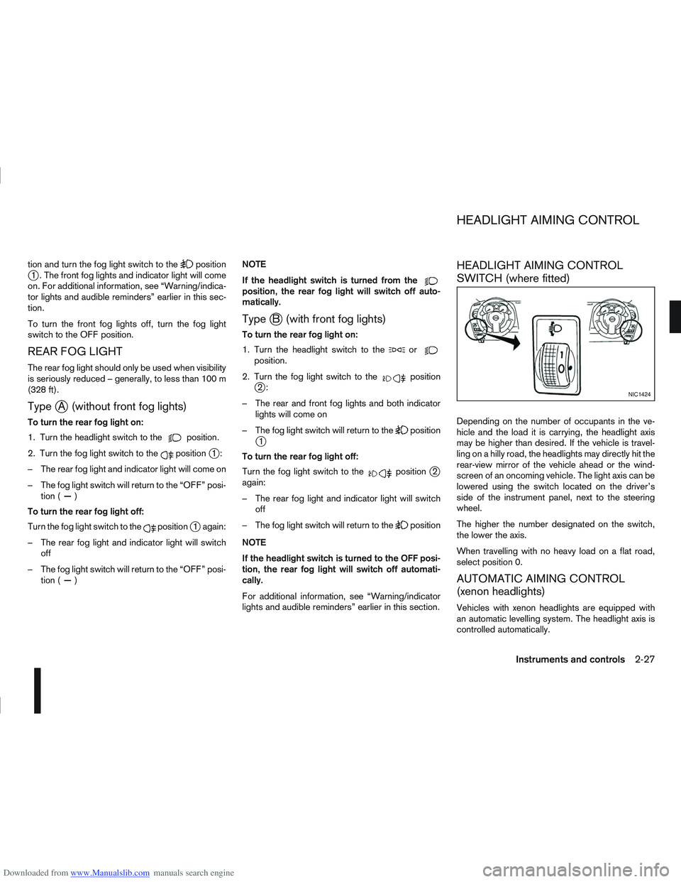
Depending on the number of occupants in the ve-
hicle and the load it is carrying, the headlight axis
may be higher than desired. If the vehicle is travel-
ling on a hilly road, the headlights may directly hit the
rear-view mirror of the vehicle ahead or the wind-
screen of an oncoming vehicle. The light axis can be
lowered using the switch located on the driver’s
side of the instrument panel, next to the steering
wheel.
The higher the number designated on the switch,
the lower the axis.
When travelling with no heavy load on a flat road,
select position 0.
AUTOMATIC AIMING CONTROL
(xenon headlights)
Vehicles with xenon headlights are equipped with
an automatic levelling system. The headlight axis is
controlled automatically.
NIC1424
HEADLIGHT AIMING CONTROL
Instruments and controls2-27
Page 78 of 297
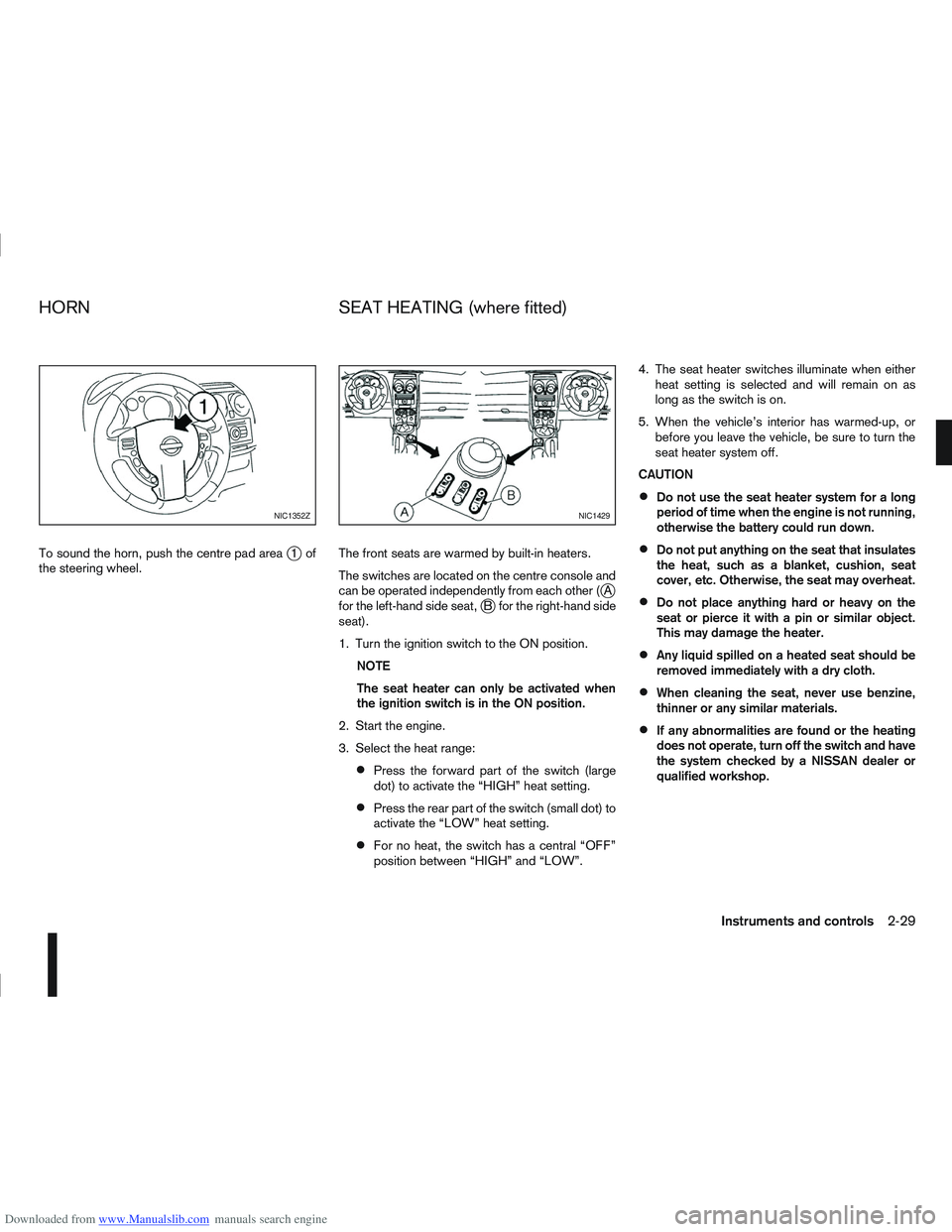
Downloaded from www.Manualslib.com manuals search engine To sound the horn, push the centre pad areaj1of
the steering wheel. The front seats are warmed by built-in heaters.
The switches are located on the centre console and
can be operated independently from each other (
jA
for the left-hand side seat,jB for the right-hand side
seat).
1. Turn the ignition switch to the ON position.
NOTE
The seat heater can only be activated when
the ignition switch is in the ON position.
2. Start the engine.
3. Select the heat range:
Press the forward part of the switch (large
dot) to activate the “HIGH” heat setting.
Press the rear part of the switch (small dot) to
activate the “LOW” heat setting.
For no heat, the switch has a central “OFF”
position between “HIGH” and “LOW”. 4. The seat heater switches illuminate when either
heat setting is selected and will remain on as
long as the switch is on.
5. When the vehicle’s interior has warmed-up, or before you leave the vehicle, be sure to turn the
seat heater system off.
CAUTION
Do not use the seat heater system for a long
period of time when the engine is not running,
otherwise the battery could run down.
Do not put anything on the seat that insulates
the heat, such as a blanket, cushion, seat
cover, etc. Otherwise, the seat may overheat.
Do not place anything hard or heavy on the
seat or pierce it with a pin or similar object.
This may damage the heater.
Any liquid spilled on a heated seat should be
removed immediately with a dry cloth.
When cleaning the seat, never use benzine,
thinner or any similar materials.
If any abnormalities are found or the heating
does not operate, turn off the switch and have
the system checked by a NISSAN dealer or
qualified workshop.
NIC1352ZNIC1429
HORN SEAT HEATING (where fitted)
Instruments and controls2-29
Page 88 of 297
Downloaded from www.Manualslib.com manuals search engine 3Pre-driving checks and adjustments
Pre-driving checks and adjustments
Keys ........................................................................\
3-2
NISSAN Anti-Theft System (NATS)* key ............. 3-2
Intelligent Key (where fitted)................................ 3-2
Key number ........................................................ 3-3
New keys ........................................................... 3-3
Emergency/mechanical key (Intelligent Key
models) .............................................................. 3-3
Integrated keyfob/remote control system .................. 3-3 Switching from Convenience mode to
Anti-hijack mode ................................................. 3-4
Using the remote keyless entry system ................ 3-5
Locking the doors ............................................... 3-5
Unlocking the doors ............................................ 3-5
Keyfob operation failure ...................................... 3-6
Intelligent Key system (where fitted) ......................... 3-6 Intelligent Key operating range ............................ 3-6
Using Intelligent Key system................................ 3-7
Locking/unlocking .............................................. 3-7
Starting the engine with the Intelligent Key .......... 3-8
Door locks ............................................................... 3-9 Super Lock system (RHD models) ...................... 3-9
Locking/unlocking with the key (vehicle dead
battery) ............................................................... 3-9 Inside door handle .............................................. 3-10
Power door lock switch ...................................... 3-10
Child safety lock — rear doors............................ 3-11
Back door lock ................................................... 3-12
Security system ....................................................... 3-13 Alarm system (where fitted) ................................ 3-13
NISSAN Anti-Theft System (NATS)..................... 3-13
Bonnet release ........................................................ 3-14
Fuel filler lid ............................................................. 3-15 Fuel filler lid opener lever .................................... 3-15
Fuel filler cap ...................................................... 3-15
Handbrake lever ...................................................... 3-16
Steering wheel......................................................... 3-16
Sun visors ............................................................... 3-17
Mirrors..................................................................... 3-17 Inside rear-view mirror ........................................ 3-17
Automatic anti-dazzling inside mirror (where
fitted).................................................................. 3-17
Outside rear-view mirrors.................................... 3-17
Vanity mirror ....................................................... 3-19
Page 103 of 297
Downloaded from www.Manualslib.com manuals search engine the fuel system and emission control system.
An incorrect cap can result in a serious mal-
function and possible injury.
CAUTION
If fuel is spilled on the vehicle body, flush it away
with water to avoid paint damage.
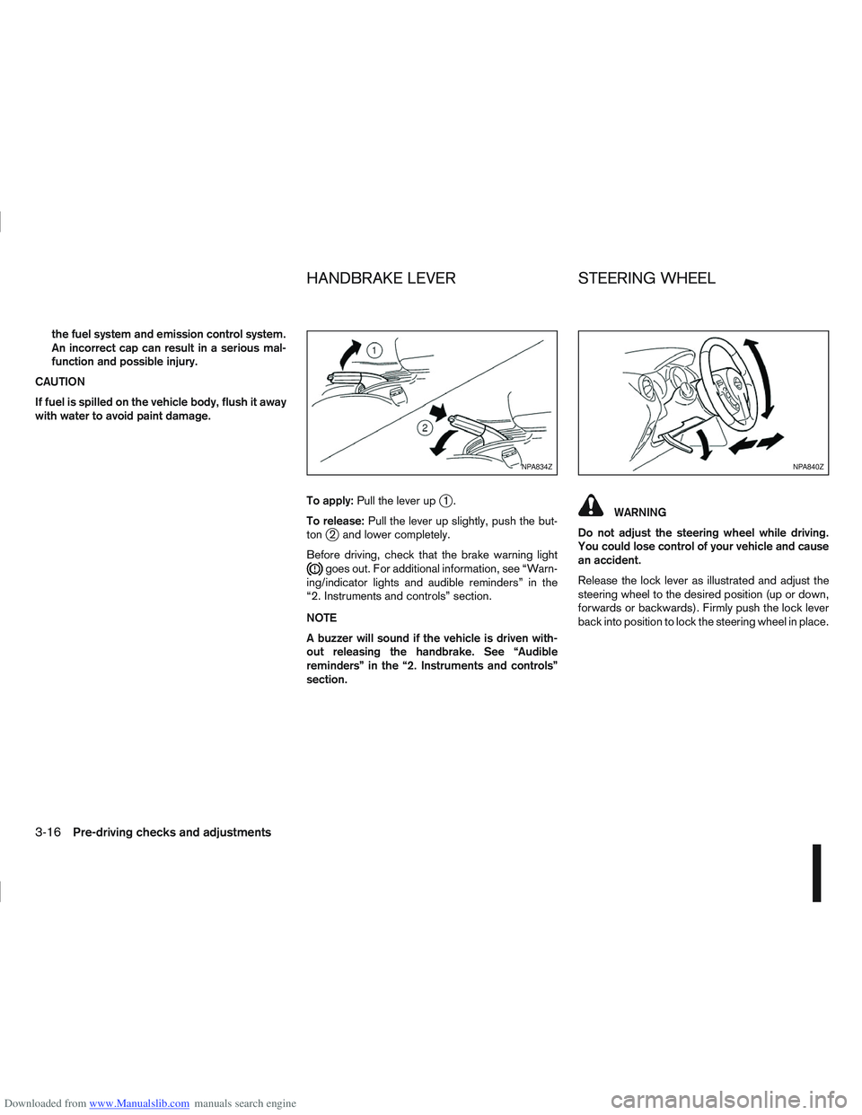
To apply:Pull the lever up
j1.
To release: Pull the lever up slightly, push the but-
ton
j2 and lower completely.
Before driving, check that the brake warning light
goes out. For additional information, see “Warn-
ing/indicator lights and audible reminders” in the
“2. Instruments and controls” section.
NOTE
A buzzer will sound if the vehicle is driven with-
out releasing the handbrake. See “Audible
reminders” in the “2. Instruments and controls”
section.
WARNING
Do not adjust the steering wheel while driving.
You could lose control of your vehicle and cause
an accident.
Release the lock lever as illustrated and adjust the
steering wheel to the desired position (up or down,
forwards or backwards). Firmly push the lock lever
back into position to lock the steering wheel in place.
NPA834ZNPA840Z
HANDBRAKE LEVER STEERING WHEEL
3-16Pre-driving checks and adjustments