2010 NISSAN LATIO 240
[x] Cancel search: 240Page 68 of 3745

TROUBLE DIAGNOSISAT-51
< SERVICE INFORMATION >
DE
F
G H
I
J
K L
M A
B
AT
N
O P
Inspections Before Trouble DiagnosisINFOID:0000000005397240
A/T FLUID CHECK
Fluid Leakage and Fluid Level Check
Check fluid leakage and check the fluid level. Refer to AT-17, "Checking A/T Fluid".
Fluid Condition Check
Check the A/T fluid condition.
STALL TEST
Stall Test Procedure
1. Check ATF and engine oil levels. If necessary, add ATF and engine oil.
2. Drive vehicle for approximately 10 minutes or until ATF and engine oil reach operating temperature.
3. Set parking brake and block wheels.
4. Install a tachometer where it can be seen by driver during test. •It is good practice to mark the point of specified engine
rpm on indicator.
5. Start engine, apply foot brake, and place selector lever in “D” position.
Fluid status Conceivable Cause Required Operation
Varnished (viscous
varnish state) Clutch, brake
scorchedReplace the ATF and check the A/T
main unit and the vehicle for mal-
functions (wire harnesses, cooler
pipes, etc.)
Milky white or
cloudy Water in the ATFReplace the ATF and check for plac-
es where water is getting in.
Large amount of
metal powder mixed
in Unusual wear of
sliding parts within
A/T
Replace the ATF and check for im-
proper operation of the A/T.
SAT638A
ATF operating temperature: 50 - 80
°C (122 - 176 °F)
SAT647B
SAT513G
SAT775B
Revision: January 20102010 Versa
Page 257 of 3745

AT-240
< SERVICE INFORMATION >
OVERHAUL
19. Clip20. O-ring 21. O-ring
22. Oil pump housing oil seal 23. Oil pump housing 24. Outer gear
25. Inner gear 26. Oil pump cover 27. Seal ring
28. Oil pump assembly
1. Retaining plate 2. Driven plate3. Dish plate
4. Snap ring 5. Spring retainer assembly 6. Reverse clutch piston
SCIA5893J
Revision: January 20102010 Versa
Page 749 of 3745

BL-240
< SERVICE INFORMATION >
VEHICLE SECURITY (THEFT WARNING) SYSTEM
BACK DOOR
Check continuity between back door lock assembly connector (back
door switch) terminals 3 and 4 while pressing (closing back door)
and releasing (opening back door) switch.
OK or NG
OK1 >> (Front and rear doors) Switch circuit is OK.
OK2 >> (Back door) GO TO 4
NG >> Replace door switch.
4.CHECK BACK DOOR SWITCH GROUND
Check continuity between back door lock assembly connector D405
terminal 4 and ground.
OK or NG
OK1 >> Back door switch circuit is OK (without Intelligent Key).
OK2 >> GO TO 5 (with Intelligent Key).
NG >> Repair or replace harness.
5.CHECK BACK DOOR SWITCH SIGNAL FOR SHORT
1. Disconnect Intelligent Key unit.
2. Check continuity between BCM connector M18 terminal 30 and ground.
OK or NG
OK >> Back door switch circuit is OK.
NG >> Repair or replace harness.
6.CHECK BACK DOOR SWITCH SIGNAL FOR OPEN
1. Turn ignition switch OFF.
2. Disconnect Intelligent Key unit and BCM.
3. Check continuity between Intelligent Key unit connector M52 (A) terminal 23 and BCM connector M18 (B) terminal 30.When back door is open :
Continuity should exist.
When back door is closed : Co ntinuity should not exist.
WIIA1245E
4 - Ground: Continuity should exist.
WIIA1246E
30 - Ground : Continuity should not exist.
WIIA1299E
Revision: January 20102010 Versa
Page 1220 of 3745
DI-10
< SERVICE INFORMATION >
COMBINATION METERS
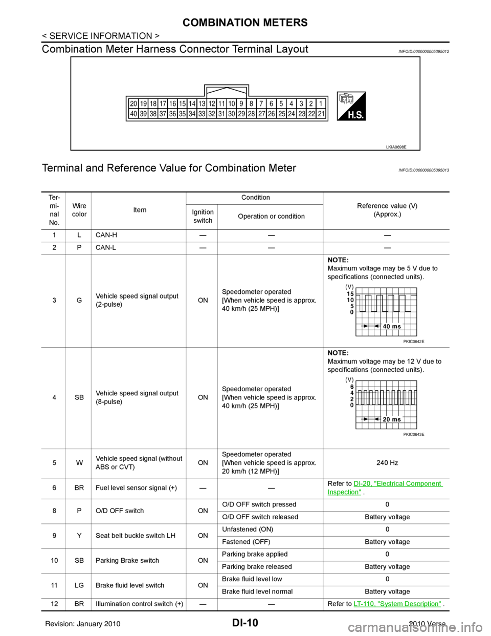
Combination Meter Harness Connector Terminal Layout
INFOID:0000000005395012
Terminal and Reference Va lue for Combination MeterINFOID:0000000005395013
LKIA0698E
Te r -
mi-nal
No. Wire
color Item Condition
Reference value (V)(Approx.)
Ignition
switch Operation or condition
1LCAN-H —— —
2PCAN-L —— —
3G Vehicle speed signal output
(2-pulse) ONSpeedometer operated
[When vehicle speed is approx.
40 km/h (25 MPH)] NOTE:
Maximum voltage may be 5 V due to
specifications (connected units).
4SB Vehicle speed signal output
(8-pulse) ONSpeedometer operated
[When vehicle speed is approx.
40 km/h (25 MPH)] NOTE:
Maximum voltage may be 12 V due to
specifications (connected units).
5W Vehicle speed signal (without
ABS or CVT) ONSpeedometer operated
[When vehicle speed is approx.
20 km/h (12 MPH)] 240 Hz
6 BR Fuel level sensor signal (+) — —Refer to DI-20, "
Electrical Component
Inspection" .
8 P O/D OFF switch ONO/D OFF switch pressed
0
O/D OFF switch released Battery voltage
9 Y Seat belt buckle switch LH ON Unfastened (ON)
0
Fastened (OFF) Battery voltage
10 SB Parking Brake switch ONParking brake applied
0
Parking brake released Battery voltage
11 LG Brake fluid level switch ON Brake fluid level low
0
Brake fluid level normal Battery voltage
12 BR Illumination control switch (+) — —Refer to LT- 11 0 , "
System Description" .
PKIC0642E
PKIC0643E
Revision: January 20102010 Versa
Page 1268 of 3745
EC-3
C
DE
F
G H
I
J
K L
M
EC A
N
O P
P0122, P0123 TP SENSOR ........................... ..165
Description .......................................................... ..165
DTC Logic .............................................................165
Wiring Diagram .....................................................166
Diagnosis Procedure .............................................166
Component Inspection ..........................................168
Special Repair Requirement .................................168
P0125 ECT SENSOR ..................................... ..169
Description .......................................................... ..169
DTC Logic .............................................................169
Diagnosis Procedure .............................................170
Component Inspection ..........................................170
P0127 IAT SENSOR .........................................172
Description .......................................................... ..172
DTC Logic .............................................................172
Diagnosis Procedure .............................................173
Component Inspection ..........................................173
P0128 THERMOSTAT FUNCTION ..................174
DTC Logic ........................................................... ..174
Diagnosis Procedure .............................................174
Component Inspection ..........................................175
P0130 A/F SENSOR 1 ......................................176
Description ............................................................176
DTC Logic .............................................................176
Component Function Check ..................................177
Wiring Diagram .....................................................179
Diagnosis Procedure .............................................179
P0131 A/F SENSOR 1 ......................................182
Description ............................................................182
DTC Logic .............................................................182
Wiring Diagram .....................................................184
Diagnosis Procedure .............................................184
P0132 A/F SENSOR 1 ......................................187
Description ............................................................187
DTC Logic .............................................................187
Wiring Diagram .....................................................189
Diagnosis Procedure .............................................189
P0133 A/F SENSOR 1 ......................................192
Description ............................................................192
DTC Logic .............................................................192
Wiring Diagram .....................................................194
Diagnosis Procedure .............................................195
P0137 HO2S2 ...................................................198
Description .......................................................... ..198
DTC Logic .............................................................198
Component Function Check ..................................199
Wiring Diagram .....................................................201
Diagnosis Procedure .............................................201
Component Inspection ..........................................203
P0138 HO2S2 ...................................................206
Description .......................................................... ..206
DTC Logic .............................................................206
Component Function Check ................................ ..207
Wiring Diagram ......................................................209
Diagnosis Procedure .............................................209
Component Inspection ...........................................212
P0139 HO2S2 ..................................................215
Description .............................................................215
DTC Logic ..............................................................215
Component Function Check ..................................216
Wiring Diagram ......................................................218
Diagnosis Procedure .............................................218
Component Inspection ...........................................220
P0171 FUEL INJECTION SYSTEM FUNC-
TION ................................................................
223
DTC Logic ..............................................................223
Wiring Diagram ......................................................225
Diagnosis Procedure .............................................225
P0172 FUEL INJECTION SYSTEM FUNC-
TION ................................................................
229
DTC Logic ..............................................................229
Wiring Diagram ......................................................231
Diagnosis Procedure .............................................231
P0181 FTT SENSOR .......................................234
Description .............................................................234
DTC Logic ..............................................................234
Wiring Diagram ......................................................236
Diagnosis Procedure .............................................236
Component Inspection ...........................................238
P0182, P0183 FTT SENSOR ..........................239
Description .............................................................239
DTC Logic ..............................................................239
Wiring Diagram ......................................................240
Diagnosis Procedure .............................................240
Component Inspection ...........................................242
P0222, P0223 TP SENSOR ............................243
Description .............................................................243
DTC Logic ..............................................................243
Wiring Diagram ......................................................244
Diagnosis Procedure .............................................244
Component Inspection ...........................................246
Special Repair Requirement ..................................246
P0300, P0301, P0302, P0303, P0304 MIS-
FIRE .................................................................
247
DTC Logic ..............................................................247
Diagnosis Procedure .............................................248
P0327, P0328 KS ............................................253
Description .............................................................253
DTC Logic ..............................................................253
Wiring Diagram ......................................................254
Diagnosis Procedure .............................................254
Component Inspection ...........................................255
P0335 CKP SENSOR (POS) ...........................257
Description .............................................................257
Revision: January 20102010 Versa
Page 1290 of 3745

INSPECTION AND ADJUSTMENTEC-25
< BASIC INSPECTION > [HR16DE]
C
D
E
F
G H
I
J
K L
M A
EC
NP
O
VIN REGISTRATION : Special Repair RequirementINFOID:0000000005398239
1.CHECK VIN
Check the VIN of the vehicle and note it. Refer to GI-43, "
Model Variation".
>> GO TO 2.
2.PERFORM VIN REGISTRATION
With CONSULT-III
1. Turn ignition switch ON and engine stopped.
2. Select “VIN REGISTRATION” in “WORK SUPPORT” mode.
3. Follow the instruction of CONSULT-III display.
>> END
ACCELERATOR PEDAL RELEAS ED POSITION LEARNING
ACCELERATOR PEDAL RELEASED PO SITION LEARNING : DescriptionINFOID:0000000005398240
Accelerator Pedal Released Position Learning is a function of ECM to learn the fully released position of the
accelerator pedal by monitoring the accelerator pedal pos ition sensor output signal. It must be performed each
time harness connector of accelerator pedal position sensor or ECM is disconnected.
ACCELERATOR PEDAL RELEASED POSITION LEARNING : Special Repair Re-
quirement
INFOID:0000000005398241
1.START
1. Make sure that accelerator pedal is fully released.
2. Turn ignition switch ON and wait at least 2 seconds.
3. Turn ignition switch OFF and wait at least 10 seconds.
4. Turn ignition switch ON and wait at least 2 seconds.
5. Turn ignition switch OFF and wait at least 10 seconds.
>> END
THROTTLE VALVE CLOSED POSITION LEARNING
THROTTLE VALVE CLOSED POSITION LEARNING : DescriptionINFOID:0000000005398242
Throttle Valve Closed Position Learning is a function of ECM to learn the fully closed position of the throttle
valve by monitoring the throttle position sensor out put signal. It must be performed each time harness connec-
tor of electric throttle contro l actuator or ECM is disconnected.
THROTTLE VALVE CLOSED POSITION LEA RNING : Special Repair Requirement
INFOID:0000000005398243
1.START
1. Make sure that accelerator pedal is fully released.
2. Turn ignition switch ON.
3. Turn ignition switch OFF and wait at least 10 seconds. Make sure that throttle valve moves during above 10 seconds by confirming the operating sound.
>> END
IDLE AIR VOLUME LEARNING
IDLE AIR VOLUME LEARNING : DescriptionINFOID:0000000005398244
Idle Air Volume Learning is a function of ECM to lear n the idle air volume that keeps each engine idle speed
within the specific range. It must be performed under any of the following conditions:
Revision: January 20102010 Versa
Page 1504 of 3745

P0182, P0183 FTT SENSOREC-239
< COMPONENT DIAGNOSIS > [HR16DE]
C
D
E
F
G H
I
J
K L
M A
EC
NP
O
P0182, P0183 FTT SENSOR
DescriptionINFOID:0000000005398406
The fuel tank temperature sensor
is used to detect the fuel tempera-
ture inside the fuel tank. The sensor modifies a voltage signal from
the ECM. The modified signal returns to the ECM as the fuel temper-
ature input. The sensor uses a ther mistor which is sensitive to the
change in temperature. The electrical resistance of the thermistor
decreases as temperature increases.
*: These data are reference values and are measured between ECM terminal 43 (Fuel tank temperature sensor) and ground.
CAUTION:
Do not use ECM ground terminals when measuring input/output vo ltage. Doing so may result in damage to the ECM's transis-
tor. Use a ground other than ECM terminals, such as the ground.
DTC LogicINFOID:0000000005398407
DTC DETECTION LOGIC
DTC CONFIRMATION PROCEDURE
1.PRECONDITIONING
If DTC Confirmation Procedure has been previously conducted, always turn ignition switch OFF and wait at
least 10 seconds before conducting the next test.
>> GO TO 2.
2.PERFORM DTC CONFIRMATION PROCEDURE
1. Turn ignition switch ON and wait at least 5 seconds.
2. Check 1st trip DTC.
Is 1st trip DTC detected?
YES >> Go to EC-240, "Diagnosis Procedure".
NO >> INSPECTION END
Fluid temperature
[° C ( °F)] Voltage*
[V] Resistance
[kΩ]
20 (68) 3.52.3 - 2.7
50 (122) 2.20.79 - 0.90
SEF012P
DTC No. Trouble diagnosis name DTC detecting condition Possible cause
P0182 Fuel tank temperature
sensor circuit low input An excessively low voltage from the sensor is
sent to ECM.
• Harness or connectors
(The sensor circuit is open or shorted.)
• Fuel tank temperature sensor
P0183 Fuel tank temperature
sensor circuit high input An excessively high voltage from the sensor is
sent to ECM.
Revision: January 20102010 Versa
Page 1505 of 3745

EC-240
< COMPONENT DIAGNOSIS >[HR16DE]
P0182, P0183
FTT SENSOR
Wiring Diagram
INFOID:0000000005398408
Diagnosis ProcedureINFOID:0000000005398409
1.CHECK GROUND CONNECTION
1. Turn ignition switch OFF.
2. Check ground connections E15, E24. Refer to EC-119, "
Ground Inspection".
Is the inspection result normal?
BBWA2636E
Revision: January 20102010 Versa