Page 682 of 3745
BACK DOOR LOCKBL-173
< SERVICE INFORMATION >
C
DE
F
G H
J
K L
M A
B
BL
N
O P
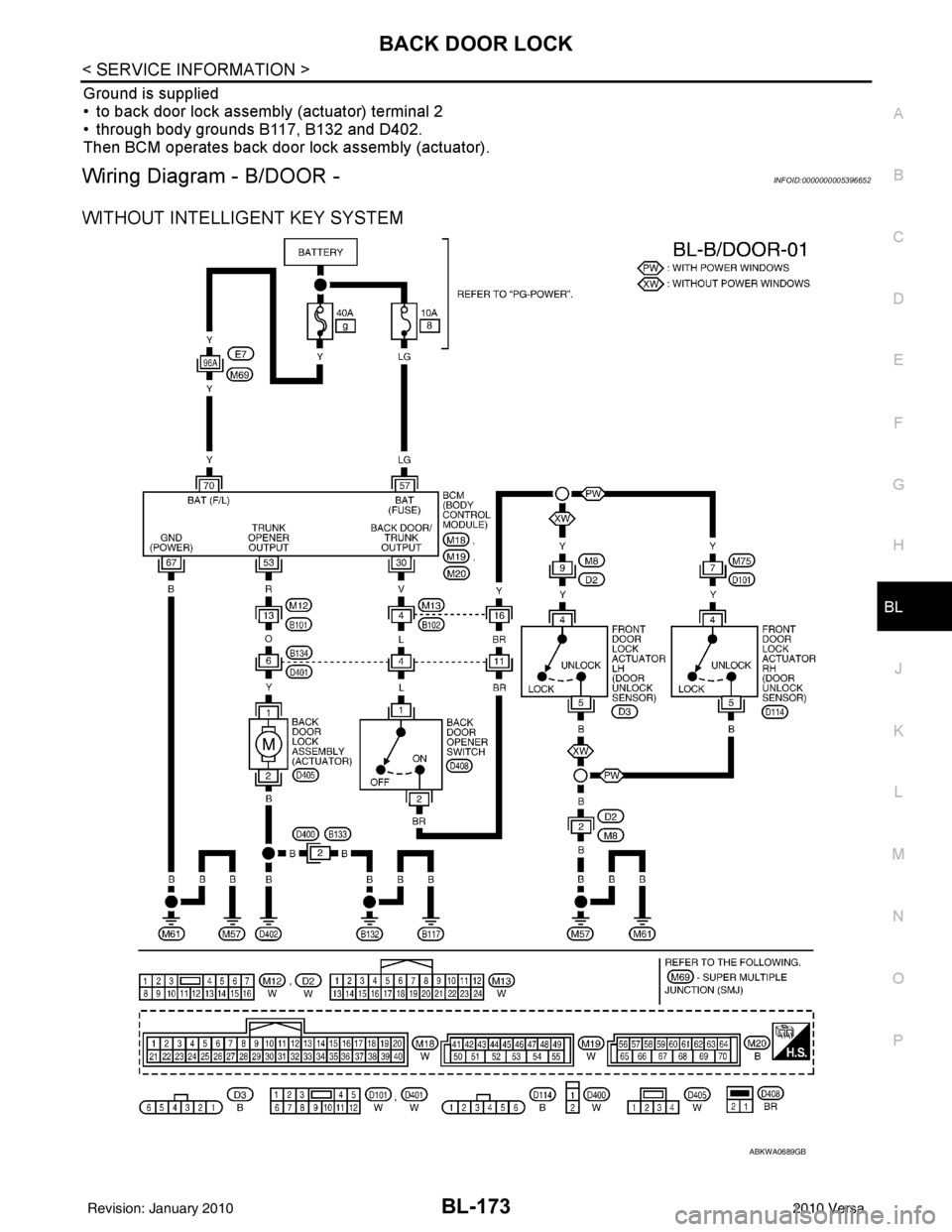
Ground is supplied
• to back door lock assembly (actuator) terminal 2
• through body grounds B117, B132 and D402.
Then BCM operates back door lock assembly (actuator).
Wiring Diagram - B/DOOR -INFOID:0000000005396652
WITHOUT INTELLIGENT KEY SYSTEM
ABKWA0689GB
Revision: January 20102010 Versa
Page 706 of 3745
TRUNK LID OPENERBL-197
< SERVICE INFORMATION >
C
DE
F
G H
J
K L
M A
B
BL
N
O P
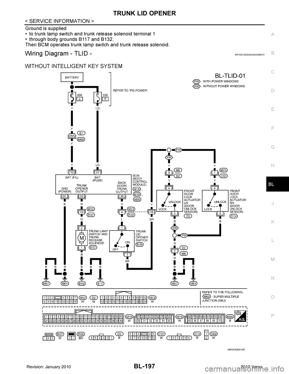
Ground is supplied
• to trunk lamp switch and trunk release solenoid terminal 1
• through body grounds B117 and B132.
Then BCM operates trunk lamp switch and trunk release solenoid.
Wiring Diagram - TLID -INFOID:0000000005396670
WITHOUT INTELLIGENT KEY SYSTEM
ABKWA0691GB
Revision: January 20102010 Versa
Page 732 of 3745
VEHICLE SECURITY (THEFT WARNING) SYSTEMBL-223
< SERVICE INFORMATION >
C
DE
F
G H
J
K L
M A
B
BL
N
O P
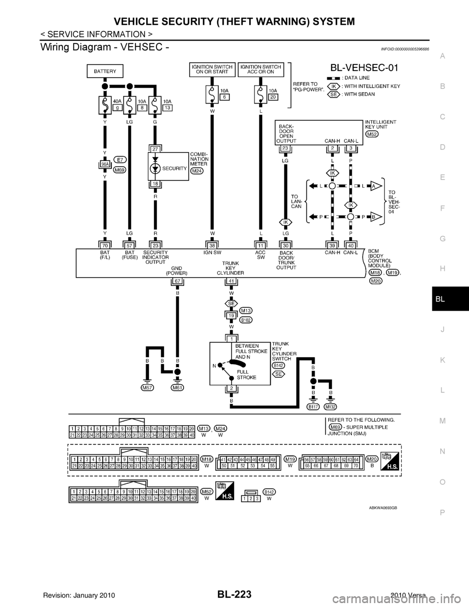
Wiring Diagram - VEHSEC -INFOID:0000000005396686
ABKWA0693GB
Revision: January 20102010 Versa
Page 760 of 3745
NATS (NISSAN ANTI-THEFT SYSTEM)BL-251
< SERVICE INFORMATION >
C
DE
F
G H
J
K L
M A
B
BL
N
O P
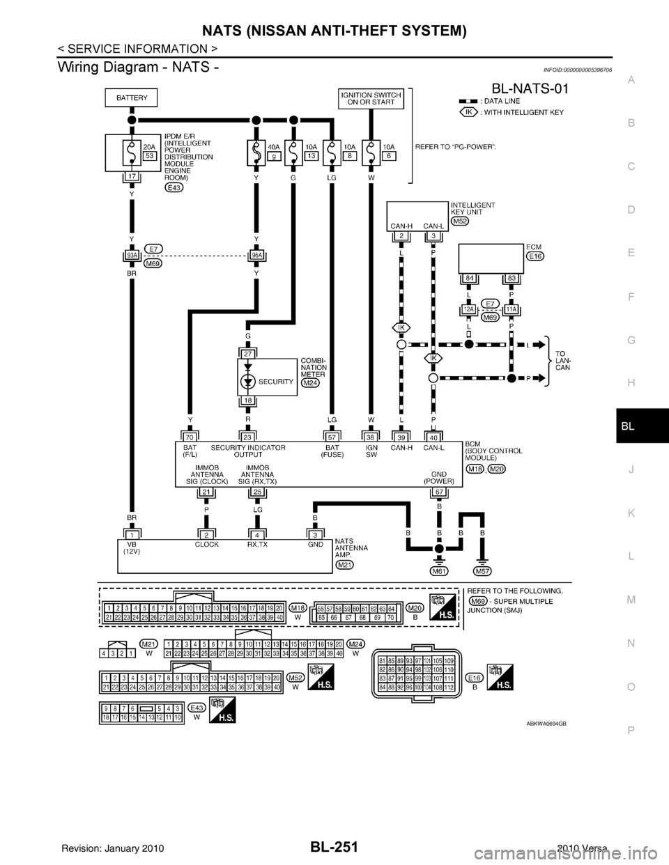
Wiring Diagram - NATS -INFOID:0000000005396706
ABKWA0694GB
Revision: January 20102010 Versa
Page 891 of 3745

BRC-1
BRAKES
C
DE
G H
I
J
K L
M
SECTION BRC
A
B
BRC
N
O P
CONTENTS
BRAKE CONTROL SYSTEM
ABS
SERVICE INFORMATION .. ..........................
3
PRECAUTIONS .............................................. .....3
Precaution for Supplemental Restraint System
(SRS) "AIR BAG" and "SEAT BELT PRE-TEN-
SIONER" ............................................................. ......
3
Precaution Necessary for Steering Wheel Rota-
tion After Battery Disconnect ............................... ......
3
Precaution for Brake System ....................................4
Precaution for Brake Control .....................................4
Precaution for CAN System ................................ ......4
PREPARATION ...................................................6
Special Service Tool ........................................... ......6
Commercial Service Tool ..........................................6
SYSTEM DESCRIPTION .....................................7
System Component ............................................. ......7
ABS Function ............................................................7
EBD Function ............................................................7
Fail-Safe Function .....................................................7
Hydraulic Circuit Diagram .........................................8
CAN COMMUNICATION ................................ .....9
System Description ............................................. ......9
TROUBLE DIAGNOSIS .....................................10
How to Perform Trouble Diagnosis for Quick and
Accurate Repair ......................................................
10
Component Parts and Harness Connector Loca-
tion ...................................................................... ....
13
Schematic ...............................................................14
Wiring Diagram - ABS - ...........................................15
Basic Inspection .................................................. ....18
Warning Lamp and Indicator Timing .......................19
Control Unit Input/Output Signal Standard ..............19
CONSULT-III Function (ABS) .................................20
TROUBLE DIAGNOSIS FOR SELF-DIAG-
NOSTIC ITEMS ..................................................
26
Wheel Sensor System ......................................... ....26
ABS Control Unit Inspection ....................................27
Solenoid Valve System Inspection ..........................27
Actuator Motor, Motor Relay, and Circuit Inspec-
tion ....................................................................... ....
28
ABS Control Unit Power and Ground Systems In-
spection ...................................................................
29
CAN Communication System Inspection .................30
TROUBLE DIAGNOSES FOR SYMPTOMS .....31
ABS Works Frequently ............................................31
Unexpected Pedal Action ........................................31
Long Stopping Distance ..........................................32
ABS Does Not Work ................................................32
Pedal Vibration or ABS Operation Noise .................32
WHEEL SENSORS ...........................................34
Removal and Installation ..................................... ....34
SENSOR ROTOR ..............................................36
Removal and Installation .........................................36
ACTUATOR AND ELECTRIC UNIT (ASSEM-
BLY) ..................................................................
37
Removal and Installation .........................................37
VDC/TCS/ABS
SERVICE INFORMATION .. .........................
39
PRECAUTIONS .................................................39
Precaution for Supplemental Restraint System
(SRS) "AIR BAG" and "SEAT BELT PRE-TEN-
SIONER" ............................................................. ....
39
Precaution Necessary for Steering Wheel Rota-
tion After Battery Disconnect ...................................
39
Precaution for Brake System ...................................40
Precaution for Brake Control ...................................40
Precaution for CAN System .....................................41
PREPARATION .................................................42
Special Service Tool ................................................42
Commercial Service Tool ........................................42
Revision: January 20102010 Versa
Page 892 of 3745

BRC-2
SYSTEM DESCRIPTION ................................ ...43
System Component ............................................. ...43
ABS Function ....................................... ...................43
EBD Function ...................................................... ...43
TCS Function ..........................................................44
VDC Function .........................................................44
Wheel Sensors .......................................................44
Fail-Safe Function ..................................................44
Hydraulic Circuit Diagram .......................................45
CAN COMMUNICATION ...................................46
System Description .................................................46
TROUBLE DIAGNOSIS .....................................47
How to Perform Trouble Diagnosis for Quick and
Accurate Repair ................................................... ...
47
Component Parts and Harness Connector Loca-
tion ..........................................................................
50
Schematic ...............................................................51
Wiring Diagram - VDC - ..........................................52
Basic Inspection .....................................................56
Warning Lamp and Indicator Timing .......................57
Control Unit Input/Output Signal Standard .............57
CONSULT-III Function (ABS) .................................60
TROUBLE DIAGNOSIS FOR SELF-DIAG-
NOSTIC ITEMS ............................................... ...
67
Wheel Sensor System Inspection ...........................67
Engine System Inspection ................................... ...68
ABS/TCS/VDC Control Unit Inspection ..................68
Steering Angle Sensor System Inspection .......... ...69
Yaw Rate/Side/Decel G Sensor System Inspec-
tion ....................................................................... ...
70
Solenoid and VDC Change-Over Valve System
Inspection ...............................................................
72
Actuator Motor, Motor Relay, and Circuit Inspec-
tion ....................................................................... ...
73
Stop Lamp Switch System Inspection ....................74
ABS/TCS/VDC Control Unit Power and Ground
Systems Inspection .............................................. ...
75
Brake Fluid Level Switch System Inspection ..........76
Pressure Sensor System Inspection .......................77
Transmission Range Switch System Inspection .. ...78
CAN Communication System Inspection ................79
Component Inspection ............................................79
TROUBLE DIAGNOSES FOR SYMPTOMS .....81
ABS Works Frequently ............................................81
Unexpected Pedal Action ..................................... ...81
Long Stopping Distance ..........................................82
ABS Does Not Work ...............................................82
Pedal Vibration or ABS Op eration Noise ................82
ABS Warning Lamp Does Not Come On When Ig-
nition Switch Is Turned On ................................... ...
83
ABS Warning Lamp Stays On When Ignition
Switch Is Turned On ............................................ ...
83
Vehicle Jerks During TCS/VDC Activation ..............84
ON-VEHICLE SERVICE ....................................85
Adjustment of Steering Angle Sensor Neutral Po-
sition ..................................................................... ...
85
WHEEL SENSORS ............................................86
Removal and Installation .........................................86
SENSOR ROTOR ........................................... ...88
Removal and Installation .........................................88
ACTUATOR AND ELECTRIC UNIT (ASSEM-
BLY) ................................................................ ...
89
Removal and Installation .........................................89
STEERING ANGLE SENSOR ........................ ...91
Removal and Installation .........................................91
G SENSOR ........................................................92
Removal and Installation .........................................92
Revision: January 20102010 Versa
Page 898 of 3745
BRC-8
< SERVICE INFORMATION >[ABS]
SYSTEM DESCRIPTION
2. For EBD malfunction, the EBD and ABS become inoperat
ive, and the condition of the vehicle is the same
as the condition of vehicles without ABS or EBD system.
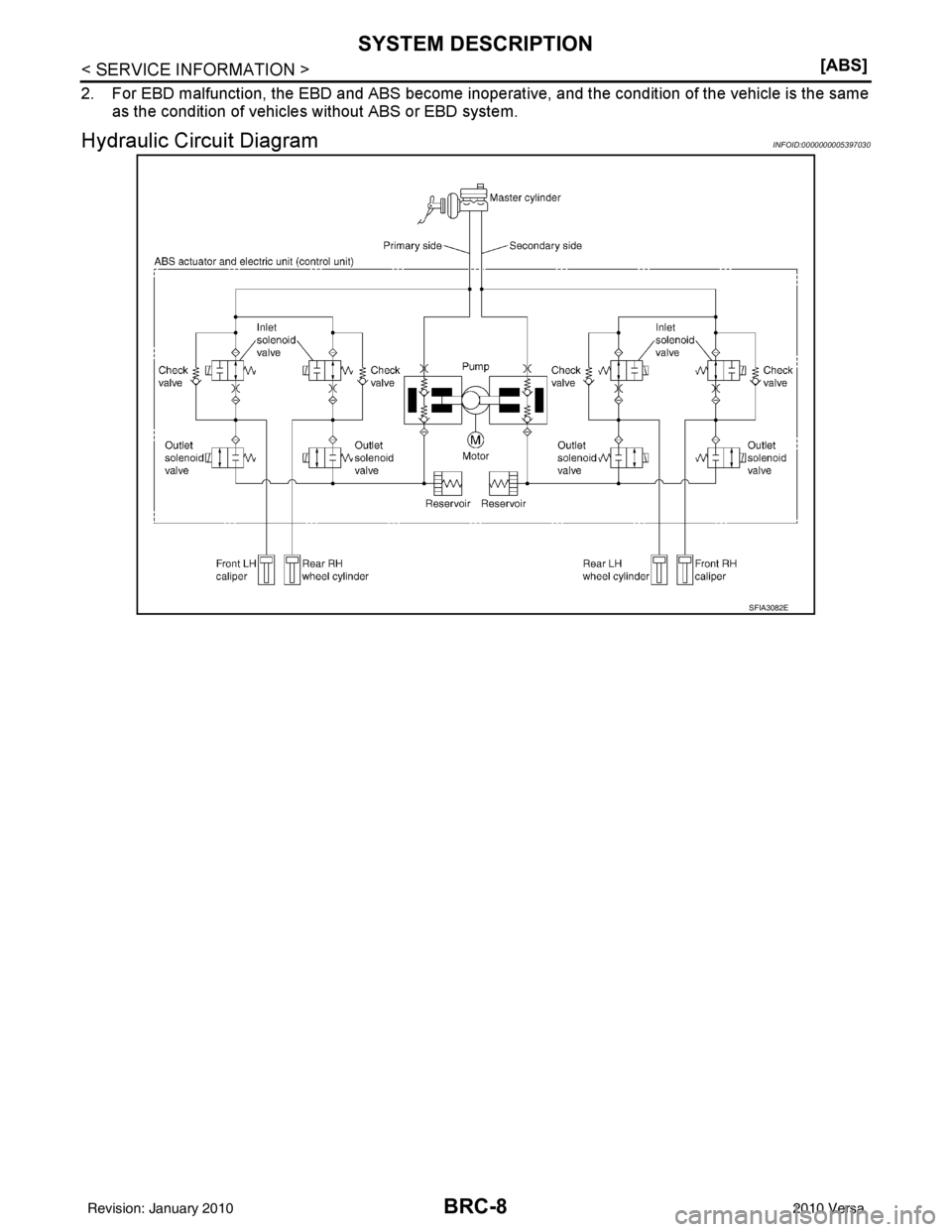
Hydraulic Circuit DiagramINFOID:0000000005397030
SFIA3082E
Revision: January 20102010 Versa
Page 905 of 3745
TROUBLE DIAGNOSISBRC-15
< SERVICE INFORMATION > [ABS]
C
D
E
G H
I
J
K L
M A
B
BRC
N
O P
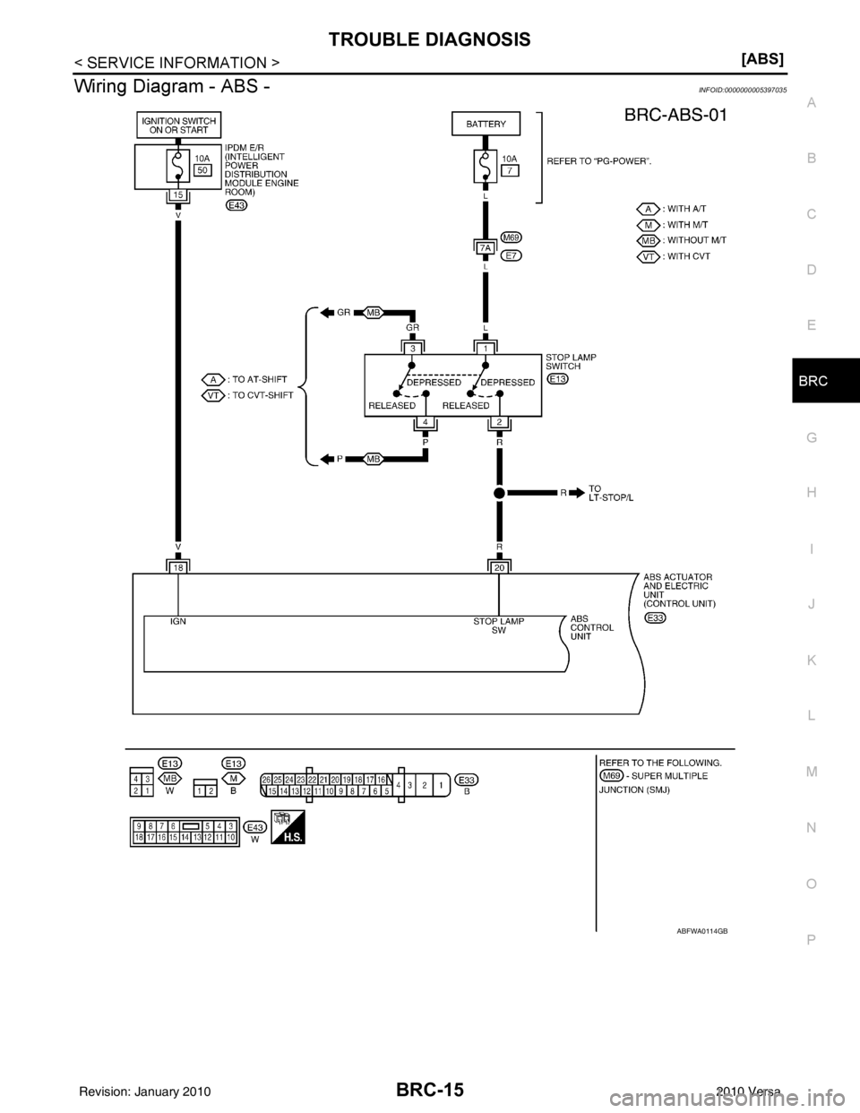
Wiring Diagram - ABS -INFOID:0000000005397035
ABFWA0114GB
Revision: January 20102010 Versa