Page 3035 of 3745
LT-40
< SERVICE INFORMATION >
HEADLAMP (FOR CANADA) - DAYTIME LIGHT SYSTEM -
2. Remove the headlamp. Refer to LT-26, "Removal and Installation".
3. Turn bulb socket counterclockwise and unlock it.
4. Remove bulb from its socket.
FRONT TURN SIGNAL LAMP
1. Turn lighting switch OFF.
2. Remove the headlamp. Refer to LT-26, "
Removal and Installation".
3. Turn bulb socket counterclockwise and unlock it.
4. Remove bulb from its socket.
Removal and InstallationINFOID:0000000005394910
REMOVAL
1. Disconnect the negative battery terminal.
2. Remove front bumper fascia. Refer to EI-15
.
3. Remove headlamp bolts (A).
4. Pull headlamp (1) toward the vehicle front, disconnect connec- tor, and remove headlamp.
INSTALLATION
Installation is in the reverse order of removal.
• After installation, perform aiming adjustment. Refer to LT-38, "
Aiming Adjustment".
Disassembly and AssemblyINFOID:0000000005394911
PKIC1223E
WKIA5418E
Revision: January 20102010 Versa
Page 3036 of 3745
HEADLAMP (FOR CANADA) - DAYTIME LIGHT SYSTEM -
LT-41
< SERVICE INFORMATION >
C
D E
F
G H
I
J
L
M A
B
LT
N
O P
DISASSEMBLY
1. Remove back cover.
2. Unlock retaining spring and remove bulb (High/Low).
3. Turn parking (clearance) lamp bulb socket counterclockwise and unlock it.
4. Remove parking (clearance) lamp bulb from its socket.
5. Turn front turn signal lamp bulb socket counterclockwise and unlock it.
6. Remove front turn signal lamp bulb from its socket.
7. Remove the bumper stay.
ASSEMBLY
Assembly is in the reverse order of disassembly.
CAUTION:
• After installing bulb, be sure to install plastic cap securely to insure water tight seal.
1. Retaining spring 2. Parking (clearance) lamp bulb 3. Parking (clearance) lamp bulb socket
4. Halogen bulb (High/Low) 5. Back cover6. Front turn signal lamp bulb socket
7. Front turn signal lamp bulb 8. Headlamp housing assembly 9. Bumper stay
A. Screw
Revision: January 20102010 Versa
Page 3045 of 3745
LT-50
< SERVICE INFORMATION >
FRONT FOG LAMP
Bulb Replacement
INFOID:0000000005394925
1. Turn lighting switch OFF.
2. Partially remove the fender protector (front) to obtain work space between the fender protector and fender.
3. Disconnect front fog lamp connector (1).
4. Turn bulb socket (2) counterclockwise unlock and remove it.
5. Remove bulb from its socket.
Removal and InstallationINFOID:0000000005394926
REMOVAL
1. Partially remove the fender protector and undercover to obtain work space between the fender protector
and fender.
2. Disconnect front fog lamp connector.
3. Release the pawl, and remove the front bumper finisher from the front bumper.
4. Remove bolt and remove front fog lamp from bracket.
INSTALLATION
Installation is in the reverse order of removal.
PKIC1071E
1. Front fog lamp 2. Front bumper finisher3. Bolt
WKIA5420E
Revision: January 20102010 Versa
Page 3080 of 3745

PARKING, LICENSE PLATE AND TAIL LAMPS
LT-85
< SERVICE INFORMATION >
C
D E
F
G H
I
J
L
M A
B
LT
N
O P
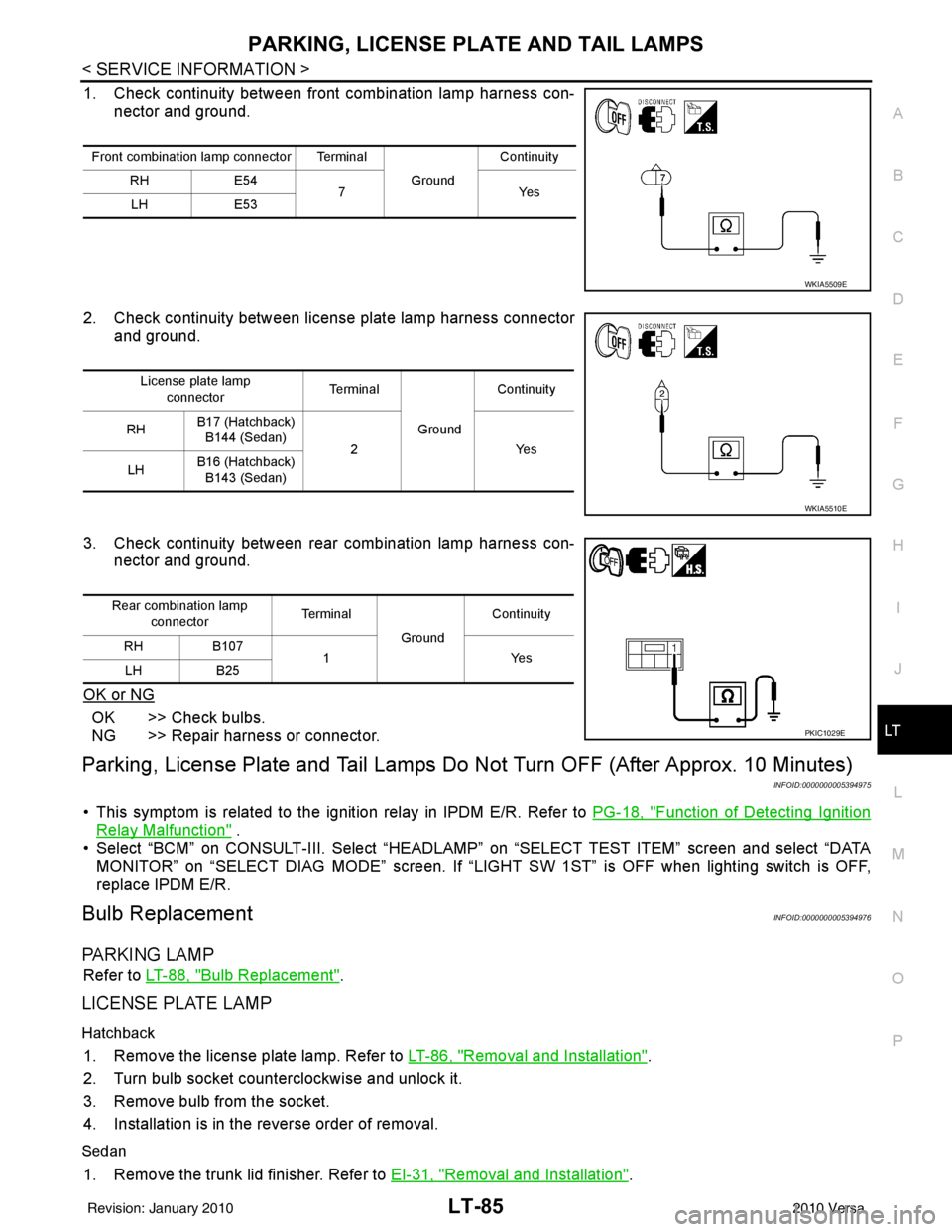
1. Check continuity between front combination lamp harness con- nector and ground.
2. Check continuity between license plate lamp harness connector and ground.
3. Check continuity between rear combination lamp harness con- nector and ground.
OK or NG
OK >> Check bulbs.
NG >> Repair harness or connector.
Parking, License Plate and Tail Lamps Do Not Turn OFF (After Approx. 10 Minutes)
INFOID:0000000005394975
• This symptom is related to the ignition relay in IPDM E/R. Refer to PG-18, "Function of Detecting Ignition
Relay Malfunction" .
• Select “BCM” on CONSULT-III. Select “HEADLAMP” on “SELECT TEST ITEM” screen and select “DATA MONITOR” on “SELECT DIAG MODE” sc reen. If “LIGHT SW 1ST” is OFF when lighting switch is OFF,
replace IPDM E/R.
Bulb ReplacementINFOID:0000000005394976
PA R K I N G L A M P
Refer to LT-88, "Bulb Replacement".
LICENSE PLATE LAMP
Hatchback
1. Remove the license plate lamp. Refer to LT-86, "Removal and Installation".
2. Turn bulb socket counterclockwise and unlock it.
3. Remove bulb from the socket.
4. Installation is in the reverse order of removal.
Sedan
1. Remove the trunk lid finisher. Refer to EI-31, "Removal and Installation".
Front combination lamp connector Terminal
GroundContinuity
RH E54
7Y es
LH E53
WKIA5509E
License plate lamp
connector Te r m i n a l
GroundContinuity
RH B17 (Hatchback)
B144 (Sedan) 2 Yes
LH B16 (Hatchback)
B143 (Sedan)
WKIA5510E
Rear combination lamp connector Te r m i n a l
GroundContinuity
RH B107
1Y es
LH B25
PKIC1029E
Revision: January 20102010 Versa
Page 3083 of 3745
LT-88
< SERVICE INFORMATION >
REAR COMBINATION LAMP
REAR COMBINATION LAMP
ComponentINFOID:0000000005394978
Hatchback
Bulb ReplacementINFOID:0000000005394979
HATCHBACK
CAUTION:
It is not necessary to remove the luggage side finisher, Doing so may render the part damaged or
unusable.
Removal
1. Remove the rear combination lamp. Refer to LT-89, "Removal and Installation".
2. Turn bulb socket counterclockwise and unlock it.
3. Remove bulb.
Installation
Installation is in the reverse order of removal.
SEDAN
Removal
1. Remove trunk side finisher. Refer to EI-57, "Removal and Installation".
LKIA0760E
1. Rear combination lamp harness 2. Turn signal lamp bulb 3. Back-up lamp bulb
4. Stop/tail lamp bulb 5. Rear combination lamp housing as-
sembly 6. Bumper stay
A. Grommet B. NutC. Clip
D. Nuts E. Clip
Revision: January 20102010 Versa
Page 3084 of 3745

REAR COMBINATION LAMPLT-89
< SERVICE INFORMATION >
C
DE
F
G H
I
J
L
M A
B
LT
N
O P
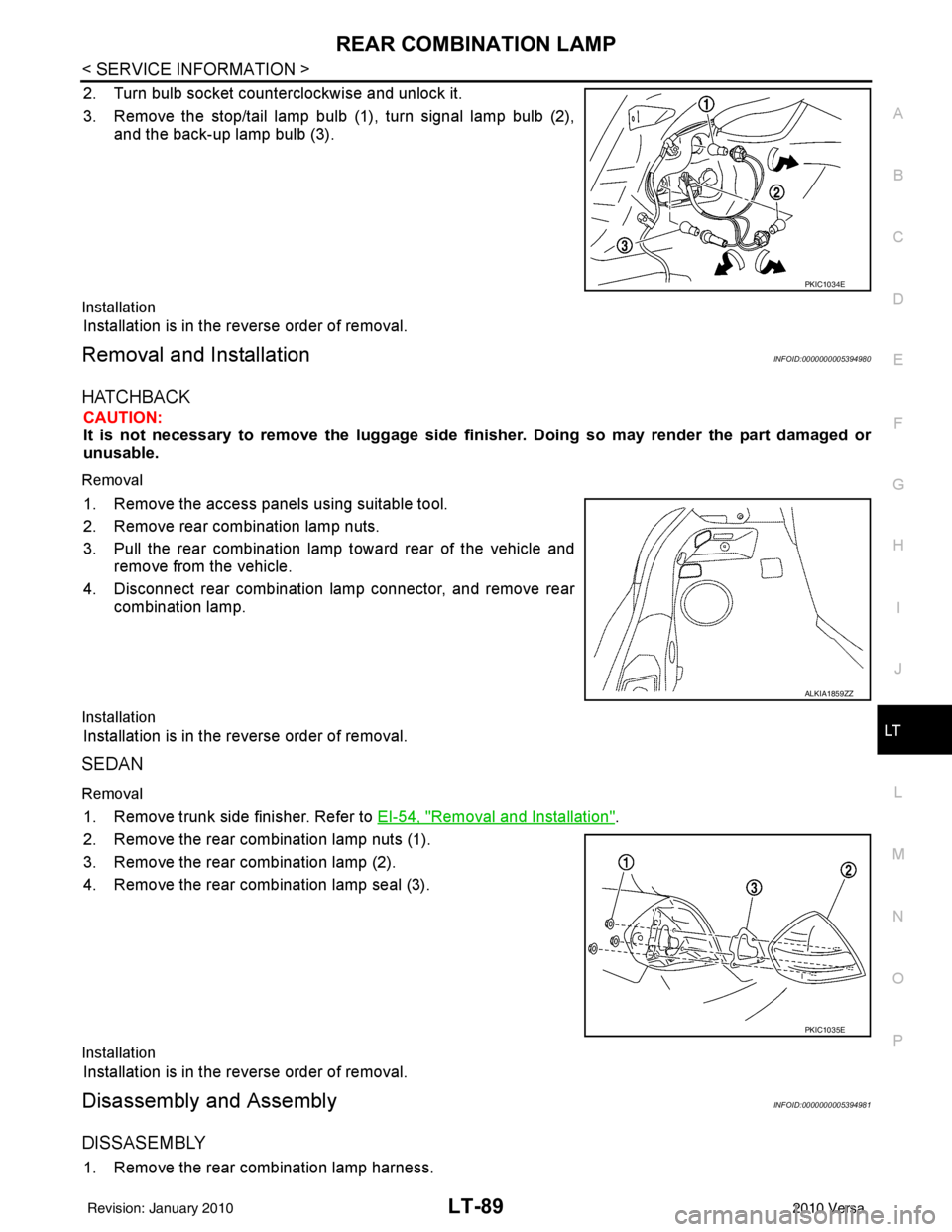
2. Turn bulb socket counterclockwise and unlock it.
3. Remove the stop/tail lamp bulb (1), turn signal lamp bulb (2), and the back-up lamp bulb (3).
Installation
Installation is in the reverse order of removal.
Removal and InstallationINFOID:0000000005394980
HATCHBACK
CAUTION:
It is not necessary to remove the lu ggage side finisher. Doing so may render the part damaged or
unusable.
Removal
1. Remove the access panels using suitable tool.
2. Remove rear combination lamp nuts.
3. Pull the rear combination lamp toward rear of the vehicle and remove from the vehicle.
4. Disconnect rear combination lamp connector, and remove rear combination lamp.
Installation
Installation is in the reverse order of removal.
SEDAN
Removal
1. Remove trunk side finisher. Refer to EI-54, "Removal and Installation".
2. Remove the rear combination lamp nuts (1).
3. Remove the rear combination lamp (2).
4. Remove the rear combination lamp seal (3).
Installation
Installation is in the reverse order of removal.
Disassembly and AssemblyINFOID:0000000005394981
DISSASEMBLY
1. Remove the rear combination lamp harness.
PKIC1034E
ALKIA1859ZZ
PKIC1035E
Revision: January 20102010 Versa
Page 3151 of 3745

MA-16
< SERVICE INFORMATION >
ENGINE MAINTENANCE (HR16DE)
ENGINE MAINTENANCE (HR16DE)
DRIVE BELT
DRIVE BELT : CheckingINFOID:0000000005714309
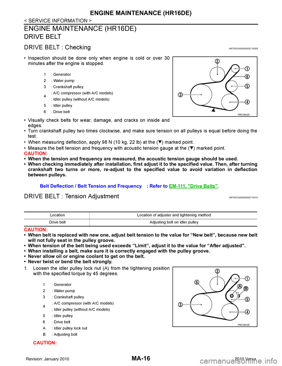
• Inspection should be done only when engine is cold or over 30minutes after the engine is stopped.
• Visually check belts for wear, damage, and cracks on inside and edges.
• Turn crankshaft pulley two times clockwise, and make sure tension on all pulleys is equal before doing the test.
• When measuring deflection, apply 98 N (10 kg, 22 lb) at the ( ) marked point.
• Measure the belt tension and frequency with acous tic tension gauge at the ( ) marked point.
CAUTION:
• When the tension and frequency are measured, the acoustic tension gauge should be used.
• When checking immediately after installation, first ad just it to the specified value. Then, after turning
crankshaft two turns or more, re-adjust to the specified value to avoid variation in deflection
between pulleys.
DRIVE BELT : Tension AdjustmentINFOID:0000000005714310
CAUTION:
• When belt is replaced with new one, adjust belt tension to the value for “New belt”, because new belt will not fully seat in the pulley groove.
• When tension of the belt being used exceeds “Limit”, adjust it to the value for “After adjusted”.
• When installing a belt, make sure it is correctly engaged with the pulley groove.
• Never allow oil or engine coolant to get on the belt.
• Never twist or bend the belt strongly.
1. Loosen the idler pulley lock nut (A) from the tightening position with the specified torque by 45 degrees.
CAUTION:
1 : Generator
2: Water pump
3 : Crankshaft pulley
4: A/C compressor (with A/C models)
: Idler pulley (without A/C models)
5 : Idler pulley
6: Drive belt
Belt Deflection / Belt Tension and Frequency : Refer to EM-111, "Drive Belts".
PBIC3642E
LocationLocation of adjuster and tightening method
Drive belt Adjusting bolt on idler pulley
1 : Generator
2: Water pump
3 : Crankshaft pulley
4 : A/C compressor
(with A/C models)
: Idler pulley (without A/C models)
5 : Idler pulley
6 : Drive belt
A : Idler pulley lock nut
B : Adjusting bolt
PBIC3643E
Revision: January 20102010 Versa
Page 3206 of 3745
MT-22
< SERVICE INFORMATION >[RS5F91R]
TRANSAXLE ASSEMBLY
DISASSEMBLY
1. Remove drain plug and gasket from clutch housing using a suitable tool and drain gear oil.
2. Remove filler plug and gasket from transaxle case.
3. Remove rear housing and O-ring.
CAUTION:
Remove to axial direction of input shaft ( ) because rear
housing oil channel is inserte d to input shaft center hole.
4. Shift control shaft shift lever (1) to the 3rd gear position. NOTE:
• If it is not shifted to the 3rd gear position, transaxle case can-
not be removed from clutch housing.
• The 3rd gear position means that control shaft select lever is
fully rotated clockwise and it is returned approximately 10
degrees.
1. Differential side bearing outer race 2. Differential side bearing 3. Speedometer drive gear
4. Pinion gear 5. Pinion shaft 6. Final drive assembly
Replace parts as a set
JPDIC0602ZZ
SCIA1709J
PCIB1524E
Revision: January 20102010 Versa